
Programming #
The NORVI EC-M11-EG-C2-B95 has a mini USB port for serial connection with the SoC for programming. Any ESP32-supported programming IDE can be used to program the controller. Follow this guide to programming NORVI ESP32-based controllers with the Arduino IDE.
SoC: ESP32-WROOM32
Programming Port: USB UART
8-pin Connector and wire harness #
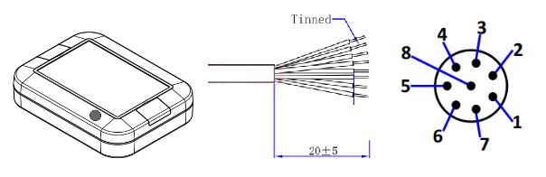
Pin Description #
| 8P Male | Wire color | I/O Configuration |
| 1 | White | Digital In 1 |
| 2 | Brown | Digital In 2 |
| 3 | Green | – |
| 4 | Yellow | – |
| 5 | Gray | RS-485A |
| 6 | Pink | RS-485B |
| 7 | Blue | Power+ |
| 8 | Red | Power- |
Digital Inputs #
Wiring Digital Inputs #
The digital inputs of NORVI EC-M11-EG-C2-B95 can be configured as both Sink and Source connections. The inverse of the digital input polar should be supplied to the common terminal.
Programming Digital Inputs #
Reading the relevant GPIO of the ESP32 gives the value of the digital input. When the inputs are in the OFF state, the GPIO goes HIGH, and when the inputs are in the ON state, the GPIO goes LOW. Refer to the GPIO allocation table in the datasheet for the digital input GPIO.
#define INPUT1 34
void setup() {
   Serial.begin(115200);
   Serial.println("Device Starting");
   pinMode(INPUT1, INPUT);
}
void loop() {
   Serial.print(digitalRead(INPUT1));
   Serial.println("");
   delay(500);
}
RS-485 Communication #
| Driver | MAX485 |
| UART RX | GPIO4 |
| UART TX | GPIO2 |
| Flow Control | GPIO13 |
Programming RS-485 #
NORVI EC-M11-EG series RS-485 connection uses a half-duplex mode of MAX485 transmitter with UART
Communication.
#define RS485_FC 13
void setup() {
   Serial.begin(115200);
   Serial.println("Device Starting");
   pinMode(RS485_FC, OUTPUT);
}
void loop() {
  digitalWrite(RS485_FC, HIGH); // Turns on Transmitter Mode
  Serial.println("RS-485 Sending");
  delay(500);
}
NB-IoT Module #
| Modem | NB-101 |
| RX | GPIO25 |
| TX | GPIO26 |
| POWER | GPIO22 |
| RESET | GPIO32 |
Programming NB-IoT #
const int GSM_RST = 32;        // Define the pin for modem reset
const int GSM_PWR_KEY = 22;    // Define the pin for modem power key
const int MODEM_RX = 25;      // Define the pin for ESP32's RX to modem's TX
const int MODEM_TX = 26;      // Define the pin for ESP32's TX to modem's RX

void setup() {
  pinMode(GSM_RST, OUTPUT);
  pinMode(GSM_PWR_KEY, OUTPUT);
  digitalWrite(GSM_PWR_KEY, HIGH);  // Set modem to flight mode
  digitalWrite(GSM_RST, HIGH);
  delay(1000);
  digitalWrite(GSM_RST, LOW);
  delay(1000);
  digitalWrite(GSM_RST, HIGH);
  delay(1000);
  Serial.begin(9600);  // Initialize the serial monitor
  Serial2.begin(9600, SERIAL_8N1, MODEM_RX, MODEM_TX);
  // Initialize communication with modem
  Serial.println("SIM AT START >>>>>>>>>>>>>>");
  delay(2000);
  Serial.flush();
  Serial2.println("AT+NCONFIG=AUTOCONNECT,TRUE");
  delay(2000);
  while (Serial2.available()) {
    char response = Serial2.read();
    Serial.write(response);
  }
  Serial2.println("AT");
  delay(2000);
  while (Serial2.available()) {
    char response = Serial2.read();
    Serial.write(response);
  }
  Serial2.println("AT+CEREG?");
  delay(2000);
  while (Serial2.available()) {
    char response = Serial2.read();
    Serial.write(response);
  }
  Serial.flush();
}

void loop() {
  Serial.print(".");
  Serial2.println("AT");
  while (Serial2.available()) {
    char response = Serial2.read();
    Serial.write(response);
  }
  delay(5000);
  Serial2.println("AT+CEREG?");
  delay(2000);
  while (Serial2.available()) {
    char response = Serial2.read();
    Serial.write(response);
  }
}


