
Product Features #
- ESP32-WROVER-B Module
- Built-in Button on front panel
- LTE Connections
- Digital Inputs
- Analog Inputs
- DIN-Rail mount
Cellular Communication LTE1
- Module – SIM7000
- Brand Name – SIMCom
- FCC ID – 2AJYU-SIM7000
- TAC – 86615402
Cellular Communication LTE2
- Module – SIM7500
- Brand Name – SIMCom
- FCC ID – 2AQ9M-SIM7500
- TAC – 86147503
Main #
| Range of Product | NORVI AGENT 1 |
| Product type | Programmable Node |
| Certifications | EN 61131-2:2007 EN 61010-1:2010+A1:2019 EN IEC 61010-2-201:2018 2014/30/EU- Electromagnetic Compatibility (EMC) Annex III, Part B, Module C |
| Rated supply voltage | Standard 12–24V DC / Low Power : 3.3–6V DC |
| Communication | WiFI / Bluetooth LTE1 / EDGE – SIMCOM SIM7000 LTE2 / EDGE – SIMCOM SIM7500 RS-485 |
| Inputs and Outputs | 3 x Digital Inputs 3 x Analog Inputs: 0-10V |
| Displays and Visual Indicators | 4 X LED / Digital Inputs |
Complementary #
| Product Unified Code | NORVI AGENT 1-BM01-LTE |
| Product Part Numbers | NORVI AGENT 1-BM01-LTE |
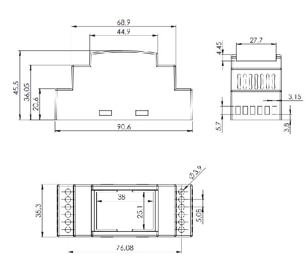
Mechanical Properties #
| Enclosure | NORVI 202 |
| Mounting / Installation Method | DIN RAIL / MOUNTING TABS |
| Terminal Type | SCREW TERMINAL |
| Terminal Arrangement | Top and Bottom |
| Length | 59.00 mm |
| Height | 86.00 mm |
| Width | 35.00 mm |
Environment #
| IP degree of protection | IP20 |
| Operating altitude | 0–2000 meters |
| Operating Temperature | – –10 … +85° C (14…185 °F) |
| Storage altitude | 0 – 3000 meters |
| Shock resistance | 15 gn for 11ms |
| Resistance to electrostatic discharge | 4kV on contact 8kV on air |
| Resistance to electromagnetic fields | 10 V/m (80 MHz …… 1GHz) 3 V/m (1.4 MHz …… 2 GHz) 1 V/m (2 MHz …… 3 GHz) |
Electrical Characteristics #
Grid-powered devices #
| Rated Supply Voltage (V) | 24V DC |
| Current Consumption (mA) | 400mA |
| Recommended Power Source | 1A 24V DC |
Processing #
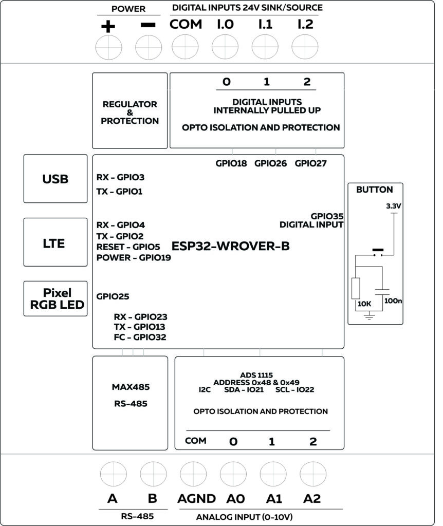
| SOC / MCU | ESP32-WROVER-B |
| Flash Memory | 4 MB |
| ROM | 448 KB |
| SRAM | 520 KB |
| PSRAM | 8 MB |
Built-in Buttons #
| Button 1 Pin | Digital Input GPIO35 |
Indicators #
| Module Type | WS2812 |
| Communication | One wire |
| Connection | GPIO25 |
INPUTS and OUTPUTS #
Digital Inputs #
| Number of Digital Inputs | 3 |
| Digital Input Polarity | Sink and Source |
| Digital Input Maximum Voltage | 32V DC |
| Digital Input Minimum Voltage | 18V DC |
| Maximum Switching Frequency | 1 kHZ |
| Terminal Arrangement | Digital Input 0 – GPIO18 Digital Input 1 – GPIO26 Digital Input 2 – GPIO27 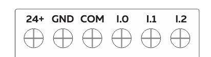 |
Analog Inputs #
| Number of Analog Inputs | 3 |
| Analog Input Measurement Range | 0 – 10V |
| Analog Input Maximum Voltage | 38V DC |
| Analog to Digital Converter (ADC) | ADS1115 |
| Analog to Digital Converter (ADC) Communication | I2C |
| Analog to Digital Converter (ADC) Address | 0x48 |
| Terminal Arrangement | A0 : Analog Input 0 – ADS1115 – 0x48 – AIN0 A1 : Analog Input 1 – ADS1115 – 0x48 – AIN1 A2 : Analog Input 2 – ADS1115 – 0x48 – AIN2 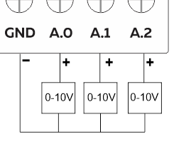 |
RS-485 Communication #
| Communication Mode | HALF-DUPLEX |
| Transceiver | MAX485 |
| Unit Load | 1/4 |
| Flow Control / Direction Control Pin | GPIO32 |
| TX Pin | GPIO13 |
| RX Pin | GPIO23 |
| Terminal Arrangement | 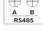 |
LTE1 Communication #
| Model of LTE Modem | SIM7000 |
| FCC ID | 2AJYU-SIM7000 |
| TAC | 86615402 |
| RXD | GPIO4 |
| TXD | GPIO5 |
| RESET | GPIO19 |
LTE2 Communication #
| Model of LTE Modem | SIM7500 |
| FCC ID | 2AQ9M-SIM7500 |
| TAC | 86147503 |
| RXD | GPIO4 |
| TXD | GPIO5 |
| RESET | GPIO19 |
GPIO Map #
| GPIO | Description | Usage |
| 0 | outputs PWM signal at boot | NRST |
| 1 | USB | TX0 |
| 2 | ||
| 3 | USB | RX0 |
| 4 | LTE Modem | RX |
| 5 | LTE Modem | TX |
| 13 | RS-485 | TX3 |
| 14 | outputs PWM signal at boot | |
| 15 | outputs PWM signal at boot | |
| 16 | ||
| 17 | ||
| 18 | input only | Digital Input 0 |
| 19 | LTE Modem | RESET |
| 20 | ||
| 22 | ||
| 23 | RS-485 | RX3 |
| 24 | ||
| 25 | Indicators | RGB LED |
| 26 | input only | Digital Input 1 |
| 27 | input only | Digital Input 2 |
| 28 | ||
| 31 | ||
| 32 | RS-485 | Flow Control |
| 33 | ||
| 35 | Button | |
| 36 |


