INTRODUCTION #
Node-RED is a powerful and visual programming tool that facilitates the creation of automation flows. This guide is designed to help set up Node-RED on Raspberry Pi HMI, enabling custom programs for industrial control.
The Raspberry Pi HMI is an all-in-one industrial controller based on the powerful Raspberry Pi CM4. It seamlessly integrates a 7-inch touch HMI, PLC functionality, and various connectivity options, making it an ideal solution for IoT applications and industrial gateways.
The Raspberry HMI supports Node-Red programs. Node-Red programming includes required nodes built for Raspberry Pi HMI by NORVI Controllers.

START WITH NODE-RED #
- Power up and turn on the Raspberry Pi HMI.
- Now follow Application Menu>Internet>Chromium Web Browser

- Now type http://localhost:1880/ on the Web Browser address bar to open Node-Red Dashboard, and press enter.

- After the node-red dashboard opens in the web browser tab click > symbol and press “ctrl+P ” to open the Toggle Palette, Click < symbol or press “ctrl+space” to open the Toggle SideBar.

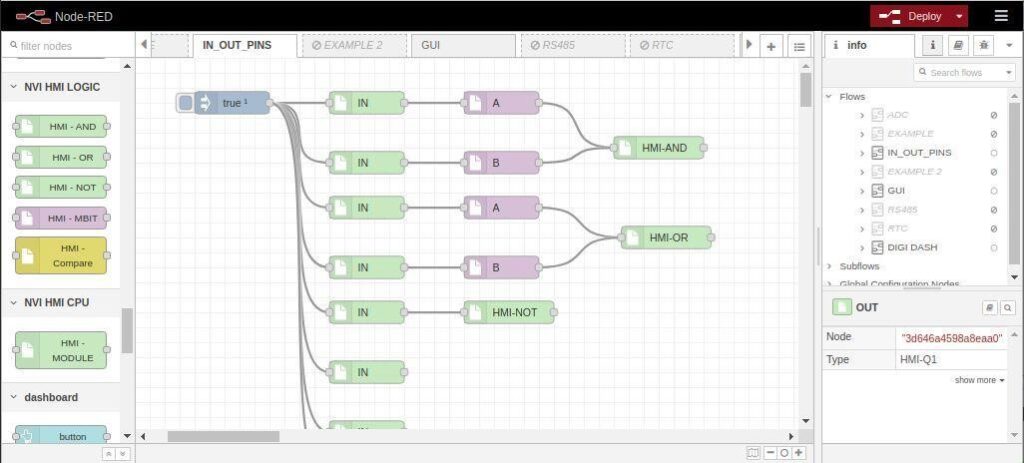
5. Go to the left “Toggle palette” and scroll down to the “NVI HDMI OUT”, “NVI HMI IN”, “NVI HMI LOGIC”, and “NVI HMI CPU” categories. Nodes in these categories can be used to program the Raspberry Pi HMI.

6. A node’s configuration can be edited by double clicking on the node, or pressing Enter when the workspace has focus. If multiple nodes are selected, the first node in the selection will be edited. The edit dialog contains three tabs:
- Properties – the edit form specific to the node type being edited.
- Description – per-node documentation formatted using Markdown. This is displayed in the Information sidebar when the node is selected.
- Appearance – options to customize the appearance of the node.

INTERFACE #
After doing all the prerequisites, let’s talk about aspects of Node RED.
- Flow
Everything in Node-RED is stored in a flow. They act as folders for the projects. Unless told specifically, the data is not shared between flows. All information processed within one flow, can’t be accessed from another.

Flows can also be enabled/disabled on request, which is handy if you want to disable one project for a while. Double-click on the tab to access the Flow Menu.

- Nodes
Nodes are classified into three main groups. It is easy to tell which group the node belongs to by looking at the connection points.
Input nodes will receive information and send it to the next node. Output nodes will send the information from the Node RED to an outside source. Function nodes will take the information in, and pass it over to the next one after processing the data.

- Deploy
After completing the stream, things are ready to be tested. To save the changes, press the DEPLOY button. This will take your script and activate it. The button comes in 3 flavors. It can deploy nodes only, stream flow, or all. Note that deploying everything restarts all nodes and may cause unwanted results.

- msg. payload
This refers to the main data or information carried by the message. It is a property of the message object (msg) and is commonly used to encapsulate the primary content or value being processed within a flow.
Here’s a simple breakdown:
Msg: This is the message object, which serves as a container for information as it flows through the Node-RED flow.
Payload: It’s a property of the message object that specifically holds the main data or value. Think of it as the payload being transported by the message.
When manipulating “msg. payload” in a Node-RED flow typically deals with the core information that the message is carrying. It could be a number, string, object, or any other type of data relevant to the specific application or task in the Node-RED program.
- Debug messages
The Debug sidebar displays messages passed to debug nodes within the flow, as well as certain log messages from the runtime. By default, the Debug sidebar shows all messages passed to it. This can be filtered by clicking the button to open the filter options panel. The Debug sidebar can only show the 100 most recent messages. If the sidebar is currently showing a filtered list of messages, the hidden messages still count towards the 100 limit. If a flow has noisy Debug nodes, rather than filter them from the sidebar it can be better to disable them by clicking their button in the workspace. The sidebar can be cleared at any time by clicking the button.

- Dashboard
This module provides a set of nodes in Node-RED to quickly create a live data dashboard. To display programs created in Node-RED, a dashboard node must be added to it.

RPI HMI CATEGORY NODES #
- NVI HMI OUT
- HMI-Q1
Digital Output node. Can be used in controlling digital outputs. Digital mode – expects a “msg. payload” with either a 0 or 1 (or true or false), and will set the selected physical pin high or low depending on the value passed in. The initial value of the pin at deployment time can also be set to 0.
Inputs: payload number | string | Boolean
Details: Digital mode – expects an msg. payload with either a 0 or 1 (or true or false), and will set the selected physical pin high or low depending on the value passed in.
The initial value of the pin at deploy time can also be set to 0
OUTPUT = SELECT OUTPUT PIN
To turn ON the OUTPUT send to “msg. payload” as TRUE
To turn OFF the OUTPUT send to “msg. payload” as FALSE

- NVI HMI IN
- HMI-I1
Digital Input Node. This particular node is purposefully crafted to symbolize the inputs of the HMI. It generates a “msg. payload” with either a 0 or 1 depending on the state of the input pin. The only work required is to correctly select the desired input in the node configuration.
Inputs: msg. payload – Boolean
The payload will be a TRUE or a FALSE.
Outputs: msg. payload – Boolean
The payload will be a TRUE or a FALSE.
TRIGGER TYPE: RISING, FALLING, BOTH
INPUT = SELECT INPUT NUMBER
DELAY TIME = INPUT TRIGGER DELAY in milliseconds.

- HMI – ADC
This Analog Input Separation Node is purposefully crafted to handle and process analog input signals. This node is particularly useful when working with sensors or devices that generate continuous analog signals, such as temperature sensors, light sensors, or pressure sensors. Users can configure the node to handle specific analog inputs by selecting the appropriate settings within the node’s properties. Users can enter the analog value and the output values to this node.
Inputs: Input HMI Analog Node
Outputs: Integer | Double Analog Value of Selected Channel
Configuration
Channel: Channel Number
Analog Value: Raw ADC Value
Output Value: Value Mapped for Raw ADC value specified in Raw ADC Value
Decimal Point: Number of decimal points to round off (Max. 3)

- HMI-ANALOG
The Analog Read Node is used to initialize the analog module and read analog channels. When integrated with Analog Input Separation Nodes, it facilitates the independent monitoring and analysis of distinct analog input signals. This synergy enables users to precisely observe and evaluate individual values, contributing to a comprehensive understanding of the analog input data within the Node-RED environment.
Inputs: Input TRUE once to initialize, Boolean
Outputs: All 8 channels are available as msg.AN0 – msg.AN7.
To extract the output for individual channels use HMI ADC Node

- NVI HMI LOGIC
- HMI-AND
The AND gate node. The output of an AND gate is TRUE only when both of the inputs “msg. payload” is TRUE. If one of the AND gate’s inputs is false, then the output of the AND gate msg. payload is FALSE. Using MBIT node you can INPUT A and B.
Inputs: Input from MBIT node | A and B
MBIT | string | Boolean
Outputs: Payload – Boolean
The payload will be a TRUE or a FALSE.
- HMI-OR
The OR gate node. The output of an OR gate is TRUE when one of the inputs “msg. payload” is TRUE. If both of the OR gate’s inputs are false, then the output of the OR gate msg. payload is FALSE. Using the MBIT node you can INPUT A and B.
Inputs: Input from MBIT node | A and B
MBIT | string | Boolean
Outputs: Payload – Boolean
The payload will be a TRUE or a FALSE.
- HMI-NOT
The NOT gate node. The purpose of this node is to invert the Boolean input.

- HMI-MBIT
Input Separation for logic gates is used to separate inputs for logic gates.
LOGIC = CONFIG as A or B.
Inputs: input for AND gate | Boolean
Output: Connected to the logic gate where the input is used.

- HMI-Compare
Compare an integer to a fixed value. It’s checking if the given integer is equal to, greater than, or less than the specified fixed value. This comparison is a fundamental operation in programming and is often used in conditional statements to make decisions based on the numerical relationship between the integer and the fixed value.
Inputs: Integer | Value to be compared
Outputs: Boolean| TRUE or FALSE
Configuration
Type: Greater than or Less than
Compare Value: Value to be compared with the input

CREATING A PROGRAM #
Here is a simple example program. It is better to start with input nodes.
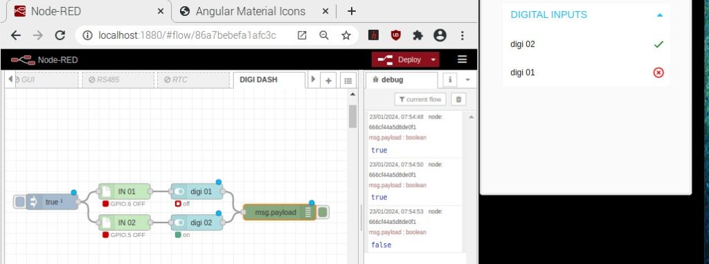
Nodes will introduce some form of data to the Node-RED server. In this example, 2 input nodes will be used. When a button is pressed it contains true and false and this represents a trigger. Here, to display the program in the Node-RED dashboard added a switch node (digi 01 & digi 02) to it as a dashboard node.


- Then add output nodes and create a program. Here, to display the program in the Node-RED dashboard added a button node (Toggle Switch7) to it as a dashboard node.


2. Programs created using HMI logic nodes. Here, to display the program in the Node-RED dashboard added a text node to it as a dashboard node.
AND Node #


OR Node #


NOT Node


3. If a debug node were added then we can display the message passed from the operation nodes in the debug window.


END OF THE NODE-RED TUTORIAL
- When the node-red program is implemented click the “Deploy” button to run the program.


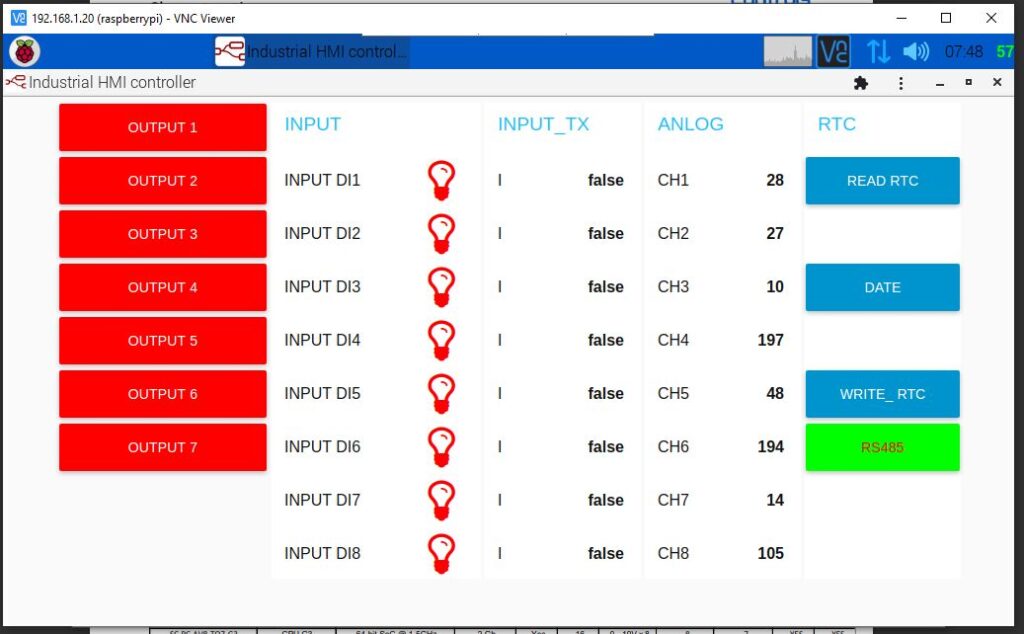
This interface offers a quick summary of the Raspberry Pi HMI’s Input/output (I/O) status. It visually represents the real-time status of connected devices such as sensors and actuators, providing a convenient overview for monitoring and control in an industrial or automated environment. When creating this program, it is necessary to add dashboard nodes individually for all input/output (I/O) programs.


