Copyright © 2024 Norvi.io
Guide for the NORVI GSM Series and MQTT SSL with an Integrated SIMCOM SIM7500 Modem.
13 min read
Table of Contents
- GITHUB REPOSITORY : SIM7500_MQTT SSL WITH DATACAKE
- MQTT PROTOCOL
- SSL MQTT Communication
- Understanding NORVI Devices with the SIM7500 Module
- Setting Up NORVI GSM series SIM7500 to MQTT SSL
- Hardware Setup
- Setting Up the MQTT Broker
- Understanding the Test program
- Software Configurations
- Integration with Data Visualization Platform
GITHUB REPOSITORY : SIM7500_MQTT SSL WITH DATACAKE #
NORVI devices are robust industrial controllers designed for IoT applications. When combined with the SIMCOM SIM7500 module and SSL configurations, these devices can leverage cellular connectivity to communicate with cloud platforms securely using the MQTT protocol.
This guide will walk through the process of setting up NORVI devices with the SSL MQTT communication on the SIMCOM SIM7500 modem using AT commands. The steps involve configuring the modem, establishing a network connection, and setting up an SSL-secured MQTT session.
MQTT PROTOCOL #
SSL MQTT Communication #
SSL with MQTT #
SSL protects data in transit from being intercepted or altered by unauthorized parties.SSL is a standard security technology that establishes an encrypted link between a server and a client. This encryption ensures that the data transmitted between the client (SIM7500 modem) and the MQTT broker is secure and protected from eavesdropping and tampering.
Configuring SSL on NORVI SIM7500 Devices #
The NORVI GSM series SIM7500 devices are robust IoT solutions that integrate the SIM7500 modem for cellular communication. When dealing with sensitive data, it’s crucial to secure communication channels. Configuring SSL on these devices ensures that data transmission between the device and the server is encrypted and secure.
To establish an SSL-encrypted MQTT connection with the NORVI SIM7500 device, follow these steps,
- Ensure the SIM card is correctly inserted into the NORVI GSM series SIM7500 device.
- Connect the NORVI device to a power source and ensure it is powered on.
- Open the serial monitor on your development environment to interact with the device.
- Configure the SIM7500 module to use SSL for MQTT communication. This involves sending specific AT commands to the module.
- Ensure your device and broker certificates are up-to-date to maintain a secure connection.
Understanding NORVI Devices with the SIM7500 Module #
NORVI devices are highly adaptable industrial IoT (Internet of Things) solutions designed to simplify the integration of sensors, actuators, and communication modules in various industrial applications. The integration of the SIM7500 module into NORVI devices enhances their capability by enabling cellular communication, which is crucial for remote monitoring, data collection, and control in areas without Wi-Fi or wired network access.
Setting Up NORVI GSM series SIM7500 to MQTT SSL #
Here we’ll be considering the NORVI GSM series SIM7500 device as a Publisher and “MQTT.FX” software as the Subscriber. With the NORVI device, we’ll be storing the I/O values in the MQTT Subscriber and the data visualization platform.
Key features of NORVI devices with the SIM7500 module,
- Industrial-grade design: Suitable for harsh environments.
- Versatile I/O options: Digital and analog inputs/outputs for various sensors and actuators.
- Cellular connectivity: LTE support via the SIM7500 module for remote monitoring and control.
- SSL/TLS security: Secure data transmission using SSL/TLS over MQTT.
Prerequisites
Before you begin, ensure you have the following,
- NORVI Device with an integrated SIM7500 module
- MQTT broker details (hostname, port, username, password)
- MQTT.fx software for testing and monitoring
- Arduino IDE and necessary libraries for programming the NORVI device.
- Data visualization platform (e.g., DATACAKE)
- SSL Certificates: ( CA certificate, client certificate, and client key).
Required Libraries
- Arduino.h
- Wire.h
- WiFi.h
- ArduinoJson.h
Sensitive Information Handling
- Secret.h: This file should contain the MQTT username and password, which should be kept secure.
SSL Certificate Setup
To establish an SSL-encrypted connection, include the SSL certificates in the code.
- Root CA Certificate: The certificate authority that issued the broker’s certificate.
- Client Certificate: Your device’s certificate.
- Client Key: The private key corresponding to the client certificate.
Hardware Setup #
1. Pin Connections
- MODEM_TX (TX Pin)
- MODEM_RX (RX Pin)
- GSM_RESET (Reset Pin)
- Digital Input Pins (D0, D1, D2, D3)
Setting Up the MQTT Broker #
MQTT Broker Configuration: #
- MQTT Broker URL (IP or domain)
- Port number (often 8883 for SSL connections)
- Username and Password (if authentication is required)
- Client ID (optional but recommended)
- Topic(s) to publish/subscribe to
Certificates #
Appropriate SSL certificates are required to establish an SSL connection.
- CA Certificate
- Client Certificate (if two-way SSL is required)
- Client Private Key (if two-way SSL is required)
Understanding the Test program #
This code is for an ESP32-based NORVI device connected to a SIMCOM SIM7500 module via UART. It sets up a secure MQTT connection using SSL, subscribes to a topic to periodically publish the status of several digital inputs to an MQTT broker. The code also handles reconnection to both the network and the MQTT broker if connections are lost.
Libraries and Includes
#include <Arduino.h>
#include <Wire.h>
#include <WiFi.h>  // Include the WiFi library for MAC address
#include <ArduinoJson.h>
#include "Secret.h" // The file to get the username and password of MQTT server
#include"datacake.h"  //includes functions for interacting with Datacake.
Define Global Variables and Constants
String gsm_send_serial(String command, int delay); //Function for sending AT commands to the GSM module.

//#define TINY_GSM_MODEM_SIM7600
#define SerialMon Serial
#define SerialAT Serial1
#define GSM_PIN ""
GPRS Credentials
// Your GPRS credentials
const char apn[] = "dialogbb";
const char gprsUser[] = "";
const char gprsPass[] = "";
MQTT Details
// MQTT details
String broker = "mqtt.datacake.co";
String MQTTport = "8883";
Sleep Settings
#define uS_TO_S_FACTOR 1000000ULL
#define TIME_TO_SLEEP 60
Pin Definitions
#define UART_BAUD 115200

#define MODEM_TX 32
#define MODEM_RX 33
#define GSM_RESET 21
#define D0 13
#define D1 34
#define D2 35
#define D3 14
#define R0 12
#define MAC_ADDRESS_SIZE 18
//Assuming MAC address is in format "XX:XX:XX:XX:XX:XX"
MAC Address
byte mac[6];
String str_macAddress;
Timing and Device Details
unsigned long prevMillis = 0;
const unsigned long interval = 60000; // Interval for sending messages

// Device-specific details
const char* deviceSerial = "*************";  // Replace with your device serial
Function Prototypes
void Init(void);       // Function prototype for network and GPRS initialization
void connectToGPRS(void);  // Function prototype for GPRS connection
void connectToMQTT(void);  // Function prototype for MQTT connection
bool isNetworkConnected(); // Function prototype to check if network is connected
bool isGPRSConnected();    // Function prototype to check if GPRS is connected
MQTT Callback Function
// Process incoming MQTT messages.
void mqttCallback(char* topic, byte* payload, unsigned int len) {
  SerialMon.print("Message arrived [");
  SerialMon.print(topic);
  SerialMon.print("]: ");
  SerialMon.write(payload, len);
  SerialMon.println();

  // Extract serial number from the topic
  String topicStr = String(topic);
  int firstSlash = topicStr.indexOf('/');
  int lastSlash = topicStr.lastIndexOf('/');
  String MAC_ID = topicStr.substring(firstSlash + 1, lastSlash);

  SerialMon.print("MAC ID: ");
  SerialMon.println(MAC_ID);

  if (MAC_ID == deviceSerial) {
    // Decode the received message
    StaticJsonDocument<200> doc;
    DeserializationError error = deserializeJson(doc, payload, len);

    if (error) {
      SerialMon.print("deserializeJson() failed: ");
      SerialMon.println(error.c_str());
      return;
    }
    // Extract the payload
     bool state = doc["state"];
  } else {
    SerialMon.println("Received message for a different serial number");
  }
}
Setup Function
void setup() {
  // Set console baud rate
  Serial.begin(115200);
  delay(10);
  SerialAT.begin(UART_BAUD, SERIAL_8N1, MODEM_RX, MODEM_TX);

  delay(2000);
  pinMode(GSM_RESET, OUTPUT);
  digitalWrite(GSM_RESET, HIGH);
  delay(2000);

  pinMode(D0, INPUT);
  pinMode(D1, INPUT);
  pinMode(D2, INPUT);
  pinMode(D3, INPUT);

  Init();
  connectToGPRS();
  connectToMQTT();
}
Main Loop
This loop ensures that the device regularly publishes its input states to the MQTT broker and stays connected to the network, handling any disconnections or errors as they occur.
void loop() {
//Check if 60 Seconds Have Passed
  if (millis() - prevMillis >= interval) {
    prevMillis = millis();

    // Read input values (assuming these are commented out for now)
    bool IN1 = digitalRead(D0);
    bool IN2 = digitalRead(D1);
    bool IN3 = digitalRead(D2);
    bool IN4 = digitalRead(D3);

    String DI0 = String(IN1 ? 1 : 0);
    String DI1 = String(IN2 ? 1 : 0);
    String DI2 = String(IN3 ? 1 : 0);
    String DI3 = String(IN4 ? 1 : 0);

WiFi.macAddress(mac);

    str_macAddress = (String(mac[0] >> 4,  HEX) + String(mac[0] & 0x0F, HEX)) +
                     (String(mac[1] >> 4,  HEX) + String(mac[1] & 0x0F, HEX)) +
                     (String(mac[2] >> 4,  HEX) + String(mac[2] & 0x0F, HEX)) +
                     (String(mac[3] >> 4,  HEX) + String(mac[3] & 0x0F, HEX)) +
                     (String(mac[4] >> 4,  HEX) + String(mac[4] & 0x0F, HEX)) +
                     (String(mac[5] >> 4,  HEX) + String(mac[5] & 0x0F, HEX));
   str_macAddress.toUpperCase();
   String Digital_input = "dtck-pub/dc_mqtt_broker/9ccc450d-96ec-4676-8e57-a3661bf528a6/D0";

    SerialMon.print("Published: ");
    SerialMon.println(DI0);

    // Send a periodic "ping" message to verify MQTT connection
    String payload=(String)(millis()/1000L);
    String response = gsm_send_serial("AT+CMQTTTOPIC=0," + String(Digital_input.length()), 1000);
    response = gsm_send_serial(Digital_input, 1000);
    response = gsm_send_serial("AT+CMQTTPAYLOAD=0,1", 1000);
    response = gsm_send_serial(DI0 + "\x1A", 1000);
    response = gsm_send_serial("AT+CMQTTPUB=0,1,60", 1000);

    // Check if the publish command was successful
      if (response.indexOf("ERROR") != -1) {
            Serial.println("MQTT publish failed. Reconnecting...");
            connectToMQTT();
            if (!isGPRSConnected()) {
                Serial.println("GPRS connection lost. Reconnecting...");
                connectToGPRS();
                connectToMQTT();
            }
            if (!isNetworkConnected()) {
                Serial.println("Network connection lost. Reconnecting...");
                Init();
                connectToGPRS();
                connectToMQTT();
            }
        }
    }
    // Handle incoming MQTT messages
    handleIncomingMessages();
}
Handling Incoming Messages
This function handles incoming MQTT messages by requesting them from the SIMCOM SIM7500 module, parsing the response, and then processing the message with a callback function.
void handleIncomingMessages() {
    while (SerialAT.available()) {
        String response = SerialAT.readStringUntil('\n');
        response.trim();

        if (response.startsWith("+CMQTTRXTOPIC")) {
            // Extract topic length
            int topicLength = response.substring(response.indexOf(",") + 1).toInt();
            SerialMon.print("Topic Length: ");
            SerialMon.println(topicLength);

            // Read the topic
            String topic = SerialAT.readStringUntil('\n');
            topic.trim();
            SerialMon.print("Topic: ");
            SerialMon.println(topic);

            // Confirm receipt of payload length
            response = SerialAT.readStringUntil('\n');
            response.trim();

            if (response.startsWith("+CMQTTRXPAYLOAD")) {
                int payloadLength = response.substring(response.indexOf(",") + 1).toInt();
                SerialMon.print("Payload Length: ");
                SerialMon.println(payloadLength);

                // Read the payload
                String payload = SerialAT.readStringUntil('\n');
                payload.trim();
                SerialMon.print("Payload: ");
                SerialMon.println(payload);

                // Ensure arrays are large enough to hold the topic and payload
                char topicArr[topicLength + 1];
                char payloadArr[payloadLength + 1];

                topic.toCharArray(topicArr, topicLength + 1);
                payload.toCharArray(payloadArr, payloadLength + 1);

                mqttCallback(topicArr, (byte*)payloadArr, payloadLength);
            }
        }
    }
}
Initialization Function
void Init(void) {
    delay(5000);
    gsm_send_serial("AT+CFUN=1", 10000);
    gsm_send_serial("AT+CPIN?", 10000);
    gsm_send_serial("AT+CSQ", 1000);
    gsm_send_serial("AT+CREG?", 1000);
    gsm_send_serial("AT+COPS?", 1000);
    gsm_send_serial("AT+CGATT?", 1000);
    gsm_send_serial("AT+CPSI?", 500);
    gsm_send_serial("AT+CGDCONT=1,\"IP\",\"dialogbb\"", 1000);
    gsm_send_serial("AT+CGACT=1,1", 1000);
    gsm_send_serial("AT+CGATT?", 1000);
    gsm_send_serial("AT+CGPADDR=1", 500);
    gsm_send_serial("AT+NETOPEN", 500);
    gsm_send_serial("AT+NETSTATE", 500);
}

void connectToGPRS(void) {
    gsm_send_serial("AT+CGATT=1", 1000);
    gsm_send_serial("AT+CGDCONT=1,\"IP\",\"dialogbb\"", 1000);
    gsm_send_serial("AT+CGACT=1,1", 1000);
    gsm_send_serial("AT+CGPADDR=1", 500);
    gsm_send_serial("AT+NETOPEN", 500);
    gsm_send_serial("AT+NETSTATE", 500);
     gsm_send_serial("AT+IPADDR", 500);
    //gsm_send_serial("AT+CTZU=1", 500);
    //gsm_send_serial("AT+CCLK=\"24/08/15,09:42:16+22\"", 500);
    gsm_send_serial("AT+CCLK?", 500);
    gsm_send_serial("AT+CGMR", 500);
    gsm_send_serial("ATI", 500);
}

void connectToMQTT(void) {
    // Upload the CA certificate
    gsm_send_serial("AT+CCERTDELE=\"server_cert.pem\"", 5000);
    gsm_send_serial("AT+CCERTLIST", 5000);
    //gsm_send_serial("AT+CCERTDOWN=\"datacake_ca.pem\"," + String(strlen(mqtt_ca_cert)), 1000);
    //int cert_length = mqtt_ca_cert.length(); // Get the length of the CA certificate

   //Construct the command string with the certificate length
   //String command5 = "AT+CCERTDOWN=\"server_cert.pem\"," + String(cert_length);
   //gsm_send_serial(command5, 2000);
   gsm_send_serial("AT+CCERTDOWN=\"server_cert.pem\",1806", 2000);

    delay(2000);
    // String command4 = mqtt_ca_cert + "\x1A";
    gsm_send_serial(mqtt_ca_cert, 2000);
    delay(2000);
    gsm_send_serial("AT+CCERTLIST", 2000);
    delay(1000);
    gsm_send_serial("AT+CSSLCFG=\"sslversion\",0,4", 2000);
    gsm_send_serial(" AT+CSSLCFG=\"authmode\",0,1", 2000);
    gsm_send_serial("AT+CSSLCFG=\"ignorelocaltime\",0,1", 2000);
    gsm_send_serial("AT+CSSLCFG=\"cacert\",0,\"server_cert.pem\"", 2000);
    gsm_send_serial("AT+CSSLCFG=\"ciphersuites\",0,0xFFFF", 2000);

    gsm_send_serial("AT+CSSLCFG=\"enableSNI\",0,1", 2000);
    gsm_send_serial("AT+CMQTTREL=0", 2000);

    gsm_send_serial("AT+CSSLCFG?", 2000);
    gsm_send_serial("AT+CCHADDR", 2000);

    gsm_send_serial("AT+CMQTTSTOP", 2000);
    gsm_send_serial("AT+CMQTTSTART", 2000);
    delay(2000);
    //gsm_send_serial(" AT+CSSLCFG=\"cacert\",1,\"datacake_ca.pem \"", 1000);
    gsm_send_serial("AT+CMQTTACCQ=0,\"PE\",1", 2000);
    delay(2000);
    gsm_send_serial("AT+CMQTTSSLCFG=0,0", 2000);
    gsm_send_serial("AT+CMQTTCFG=\"checkUTF8\",0,0", 2000);
    gsm_send_serial("AT+CSSLCFG=0", 2000);
    gsm_send_serial("AT+CMQTTWILLTOPIC=0,1", 5000);
    gsm_send_serial("p\x1A", 5000);
    gsm_send_serial("AT+CMQTTWILLMSG=0,1,1", 5000);
    gsm_send_serial("q\x1A", 5000);
    delay(2000);
    String command = "AT+CMQTTCONNECT=0,\"tcp://mqtt.datacake.co:8883\",60,1,\"" + username + "\",\"" + password + "\"";
    gsm_send_serial(command,1500);
    delay(2000);

}
Utility Functions
bool isNetworkConnected() {
    String response = gsm_send_serial("AT+CREG?", 3000);
    return (response.indexOf("+CREG: 0,1") != -1 || response.indexOf("+CREG: 0,5") != -1);
}

bool isGPRSConnected() {
    String response = gsm_send_serial("AT+CGATT?", 3000);
    return (response.indexOf("+CGATT: 1") != -1);
}

String gsm_send_serial(String command, int delay) {
    String buff_resp = "";
    Serial.println("Send ->: " + command);
    SerialAT.println(command);
    long wtimer = millis();
    while (wtimer + delay > millis()) {
        while (SerialAT.available()) {
            buff_resp += SerialAT.readString();
        }
    }
    Serial.println(buff_resp);
    return buff_resp;
}
Software Configurations #
Essential AT Commands #
After uploading the code to the NORVI GSM series device, it’s important to verify that the SIM card is correctly registered and the device is able to communicate with the network.
This can be done by checking the serial monitor for specific AT command responses.
Setting Up the MQTT Broker #
MQTT Broker Configuration #
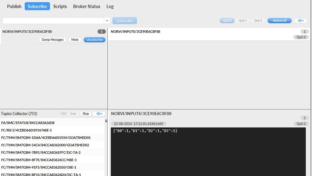
Use the MQTT.fx software as a Subscriber to set up the MQTT broker for the NORVI GSM series device.
Below is the essential information required to configure the MQTT broker.
- MQTT Broker URL (IP or domain)
- Port number
- Client ID (optional but recommended)
- Username and Password (if authentication is required)
- Topic(s) to publish/subscribe to
String Digital_input = "NORVI/INPUTS/" + str_macAddress; //MQTT TopicSteps to Configure in MQTT.fx #
Check this link for detailed instructions on how to configure the MQTT broker and the Subscriber.
- Download MQTT.fx client and install it.
- Open the MQTT.fx and click the Settings icon.
- Click + to create a profile.
- Enter the Connection Profile and General information.

- Enter the User Credentials information


- After completing the above steps, click Apply > OK to save.
- Then, select the name of the file just created in the profile box and click Connect.
- If the round icon in the top-right corner is green, the connection to IoT Hub is successful, and publishing and subscribing operations can be performed.
- Select the Subscribe tab in the client, scan and select the topic name, and click Subscribe to subscribe to the topic.
- The subscribing result can be seen in the bottom right corner.

Integration with Data Visualization Platform #
The NORVI Devices can be connected to an IoT platform, allowing users to visualize data collected by the NORVI devices. The platform used in this case is DATACAKE. Here’s how to integrate the NORVI devices with DATACAKE.
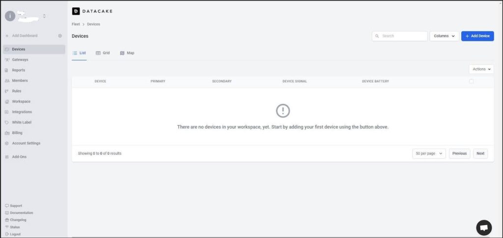
Access the DATACAKE from this link and navigate the Datacake dashboard. Select the “Add Devices”.

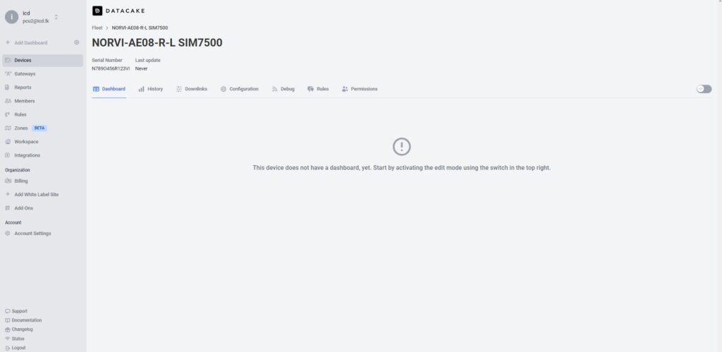
For the MQTT integration select the API. This will add the device to the Datacake account.


Click on Configuration Scroll down a bit and go to the new panel “MQTT Configuration”. Press on “Add New MQTT Broker”. Fill in the server details and add.


Then link the MQTT device on the broker to the device in the DATACAKE by providing the MQTT upline decoder. Subscribe to the topic on the MQTT broker and write a payload decoder.

This decoder function is designed to decode incoming messages from a device and format them into a structure that can be sent to the Datacake API for display or storage.
This function starts by converting the incoming payload, Extracting the MAC ID from the Topic, presumably in JSON format, into a JavaScript object. It uses JSON.parse() to accomplish this.
function Decoder(topic, payload) {
   var mac_id = topic.split("/")[2];
   payload = JSON.parse(payload);
Convert the string representations of the digital input states (which might be “true” or “false”) into integers (0 or 1).
 // Convert string "true"/"false" to integers (0 or 1)
    var D0 = JSON.parse(payload.D0) ;
    var D1 = JSON.parse(payload.D1) ;
    var D2 = JSON.parse(payload.D2);
    var D3 = JSON.parse(payload.D3);
Return an array of objects where each object contains:
device: A serial number or device ID (hard coded as “N123O456R789VI”).
field: The name of the digital input pin (“D0”, “D1”, “D2”, “D3”).
value: The state of the corresponding digital input pin (0 or 1).
//if(mac_id =="************")
 return [
        {   device: "Serial Number", // Serial Number or Device ID
            field: "D0",
            value: D0
        },
        {   device: "Serial Number", // Serial Number or Device ID
            field: "D1",
            value: D1
        },
        {   device: "Serial Number", // Serial Number or Device ID
            field: "D2",
            value: D2
        },
        {   device: "Serial Number", // Serial Number or Device ID
            field: "D3",
            value: D3
        }
    ];
}
“Try Decoder Function” allows the decoder function to be tested to verify its functionality before deploying it. By entering sample data and observing the output, you can verify that the decoder is correctly parsing incoming payloads and formatting the data in a way that can be sent to the Datacake API.

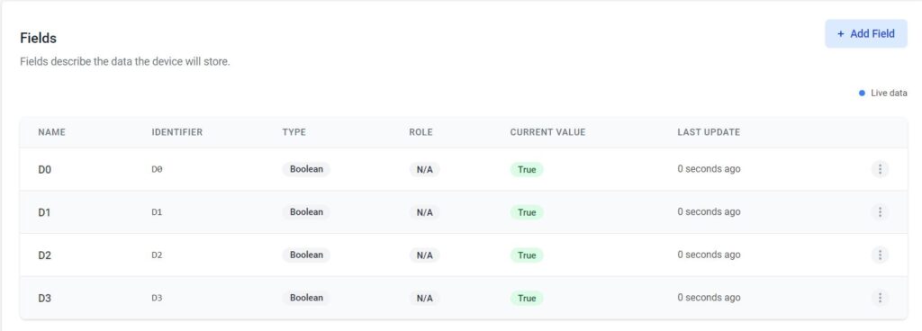
To create a first database field, click on the “Add Field”. This will open another modal asking for some required input for the fields.
When typing the name for that field, the identifier auto-fills. This identifier is unique and cannot be changed. it’s required for accessing the field from within the payload decoder or API.

If the device is already sending data, an indication of incoming data can be seen in the “Last data” column.


After the settings in the configuration section, the dashboard can be created. Use the Tab Bar on the Device to navigate into the ”Dashboard” view.


