NORVI EX-ANQ 04 – USER GUIDE
5 min read
Table of Contents
Programming #
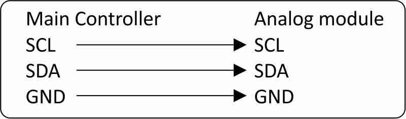
NORVI-EX-ANQ 04 uses I2C communication for Analog Outputs on devices with address configuration support. The addresses of the devices can be configured with the DIP switches at the bottom of the controller. It can Daisy chain up to 8 expansion modules. NORVI-EX-ANQ 04 module communicates with a host controller through an I2C. This allows the host controller to set output values for each channel.
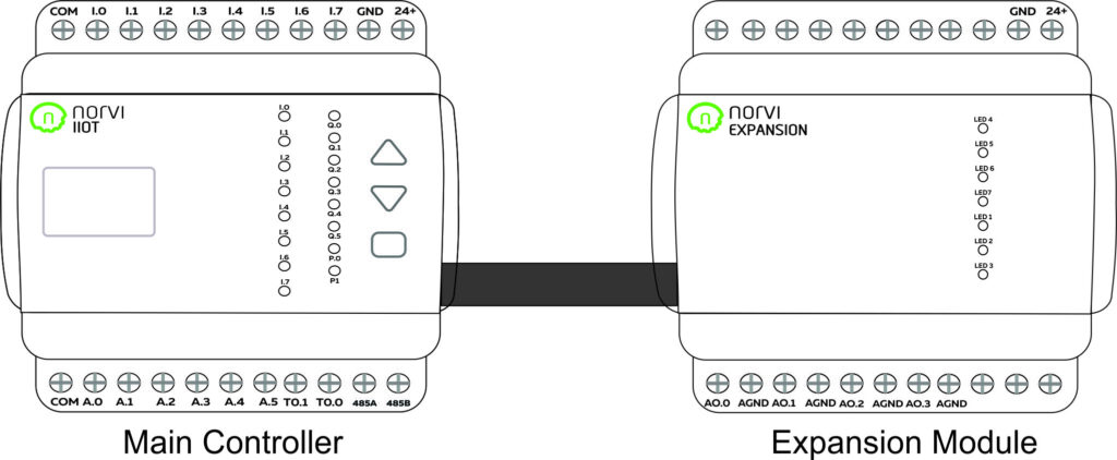
Expansion Port #
The expansion port of the NORVI IIOT Controllers can be utilized for external sensor connections where raw GPIO connections are required or they can be used to plug NORVI Expansion Modules. Connect the left side expansion port of the NORVI expansion modules and the right side expansion port of the main module using an expansion cable to connect the NORVI expansion modules.
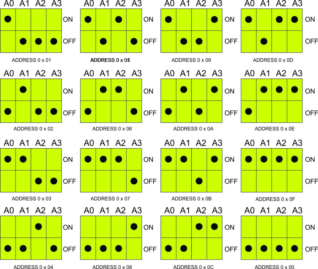
I2C Address Setting #
In the NORVI Analog output Expansion on modules with Address configuration options, the I2C Address of the expansion module can be configured by switching DIP Switches at the bottom of the expansion module. The device can be configured in 4, I2C addresses using the 4, switches.
4 – 20 mA Analog Outputs #
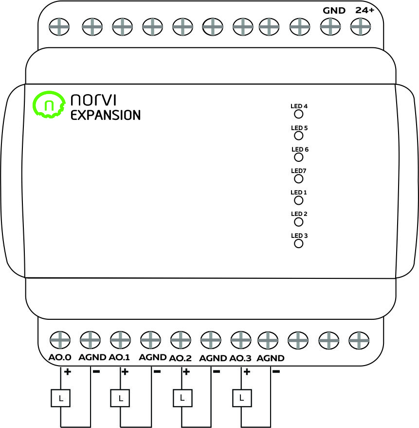
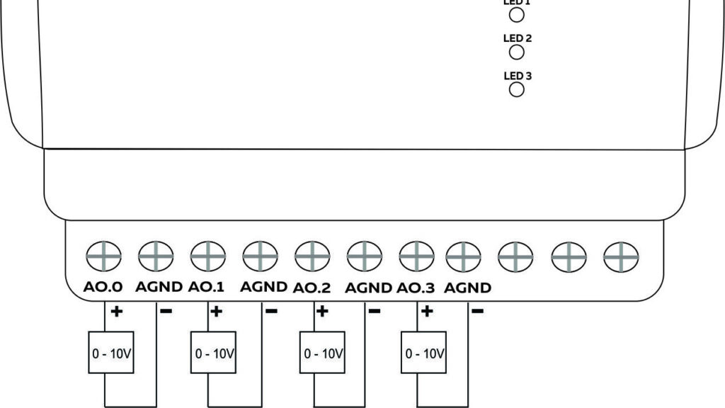
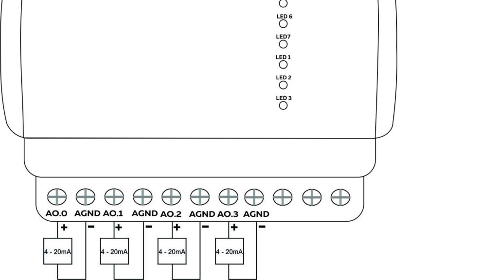
Wiring Analog Outputs #
The Analog output of the NORVI Analog output Expansion should be connected to the ground input of the controller. I2C Master can command the NORVI Analog Output expansion to output analog values.
The NORVI Analog Output expansion module provides four separate analog output channels that can be configured from the I2C. Each channel can independently generate an analog voltage or current signal.
Reading Analog Outputs #
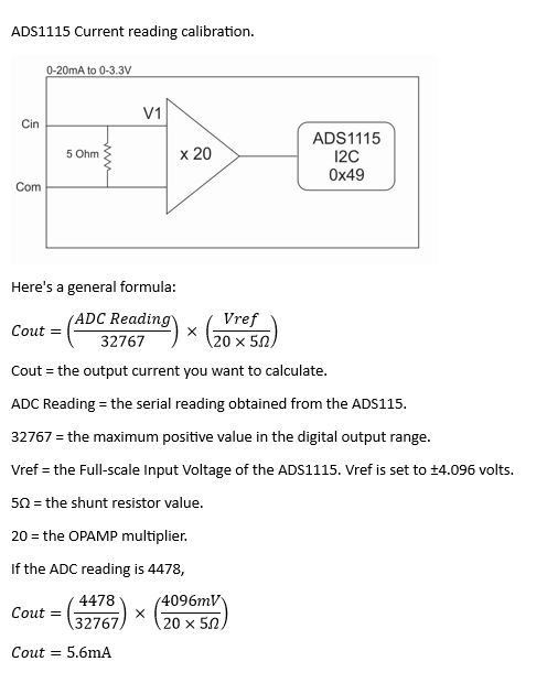
Reading the relevant I2C address of the ADC gives the value of the Analog Input.
Programming Analog Inputs #
The following example code reads the analog outputs on the NORVI analog output expansion. This example code is configured to get a 0 – 10V output from the first two channels and a 0 – 20mA output from the last two.
#include "Wire.h"
#define I2C_DEV_ADDR 0x5F
uint32_t i = 0;
unsigned int send_value = 2000;

void write_channel(byte device_address, unsigned int channel, unsigned int value) {
  unsigned int tft_value = 0;
  Wire.beginTransmission(device_address);
  Wire.write(1 + (channel * 2)); // Pointer Register
  tft_value = value >> 8;
  Wire.write(tft_value); //  Register [1] Config
  tft_value = value & 0xFF;
  Wire.write(tft_value); //  Register [1] Config
  Wire.endTransmission();
}

void config_dac(byte device_address, unsigned int c1, unsigned int c2, unsigned int c3, unsigned int c4) {
  unsigned int tft_value = 0;
  Wire.beginTransmission(device_address);
  Wire.write(0x01); // Pointer Register
  tft_value = c4 << 3;
  tft_value = tft_value | (c3 << 2);
  tft_value = tft_value | (c2 << 1);
  tft_value = tft_value | c1;
  Serial.print("BINARY PRINT  ");
  Serial.println(tft_value, BIN);
  Wire.write(tft_value); //  Register [1] Config
  Wire.endTransmission();
}

void setup() {
  Serial.begin(115200);
  Serial.setDebugOutput(true);
  Wire.begin(16, 17);
  delay(200);
  SCAN();                 // Scan and Print I2C Address of connected devices
  delay(1000);
  config_dac(I2C_DEV_ADDR,0, 0, 1, 1);
  send_value = 2000;      }

void loop() {
  config_dac(I2C_DEV_ADDR, 0, 0, 1, 1);
  for (int i = 1; i < 5; i++) {
    write_channel(I2C_DEV_ADDR, i, send_value); // Write channel sends the ADC value to the channel
    Serial.println(i);
    Serial.println(send_value);
    delay(100);
  }
  send_value = send_value + 100; // Increase output value by 100 each cycle.
  if (send_value > 4095)
    send_value = 0; // If the value exceeds 4095 , reset the value to zero
  delay(5000);
}
void SCAN() {
  byte error, address;
  int nDevices;
  Serial.println("Scanning...");
  nDevices = 0;
  for (address = 1; address < 127; address++) {
    Wire.beginTransmission(address);
    error = Wire.endTransmission();
    if (error == 0) {
      Serial.print("I2C device found at address 0x");
if (address < 16)
        Serial.print("0");
Serial.println(address, HEX);
      nDevices++;
    } else if (error == 4) {
      Serial.print("Unknown error at address 0x");
      if (address < 16)
        Serial.print("0");
      Serial.println(address, HEX);
    }
  }
  if (nDevices == 0)
    Serial.println("No I2C devices found");
  else
    Serial.println("done");
}
Example Code Functions #
| write_channel () | |
| Description | Address: I2C address of the Analog Output expansion. Channel: Number of the channel that output should be updated. Value: a 12-bit value to be written to the analog channel. |
| Syntax | write_channel (address, channel, value) |
| Parameters | Address: I2C address of the Analog Output expansion. Channel: Number of the channel that output should be updated. Value: a 12bit value to be written to the analog channel. |
| Returns | Nothing |
| config_dac () | |||
| Description | This function configures all the four channels of the I2C expansion. | ||
| Syntax | This function configures all four channels of the I2C expansion. | ||
| Parameters | Address: I2C address of the Analog Output expansion. | ||
| Channel 1: output configuration of channel 1 | 0 = 0 – 10V Output | 1 = 4 – 20mA Output | |
| Channel 2: output configuration of channel 2 | 0 = 0 – 10V Output | 1 = 4 – 20mA Output | |
| Channel 3: output configuration of channel 3 | 0 = 0 – 10V Output | 1 = 4 – 20mA Output | |
| Channel 4: output configuration of channel 4 | 0 = 0 – 10V Output | 1 = 4 – 20mA Output | |
| Returns | Nothing | ||
I2C Control From a master #
| Control Register | ||
| Bit Position | Description | Values |
| B7 | ||
| B6 | ||
| B5 | ||
| B4 | ||
| B3 | Analog Channel D Config | 0 = 0 – 10V 1 = 4 – 20mA |
| B2 | Analog Channel C Config | 0 = 0 – 10V 1 = 4 – 20mA |
| B1 | Analog Channel B Config | 0 = 0 – 10V 1 = 4 – 20mA |
| B0 | Analog Channel A Config | 0 = 0 – 10V 1 = 4 – 20mA |
| Status Register | |||
| Bit Position | Description | 0 – 10V Output Mode | 4 – 20mA Output Mode |
| B7 | AVDD Power Supply Monitor Error. | ||
| B6 | Power Supply Monitor Error | ||
| B5 | Charge pump error detected | ||
| B4 | High temperature detected | ||
| B3 | Channel D Status | 1 = Short Circuit 0 = Normal | 1 = Open Circuit 0 = Normal |
| B2 | Channel C Status | 1 = Short Circuit 0 = Normal | 1 = Open Circuit 0 = Normal |
| B1 | Channel B Status | 1 = Short Circuit 0 = Normal | 1 = Open Circuit 0 = Normal |
| B0 | Channel A Status | 1 = Short Circuit 0 = Normal | 1 = Open Circuit 0 = Normal |
| Bit Position | B7 | B6 | B5 | B4 | B3 | B2 | B1 | B0 |
| Analog Output 1 | 12 bit ADC Code Last 12 bits will affect the output 4095 = 10V / 20mA 0 = 0V / 0mA | |||||||
| Analog Output 1 | ||||||||
| Analog Output 1 | ||||||||
| Analog Output 1 | ||||||||


