EC-M11-BC-C2-B95 – USER GUIDE
2 min read
Table of Contents
Programming #
The NORVI EC-M11-BC-C2-B95 has a mini USB port for serial connection with the SoC for programming. Any ESP32-supported programming IDE can be used to program the controller. Follow this guide to programming NORVI ESP32-based controllers with the Arduino IDE.
SoC: ESP32-WROOM32
Programming Port: USB UART
Wiring digital inputs, 12V power outputs, and solar #
8-pin and 3-pin connectors and wire harness #
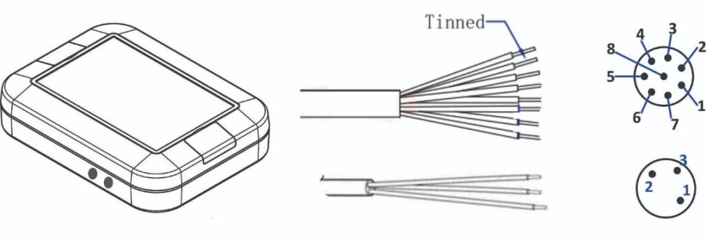
Pin Description #
| 8P Male | Wire color | I/O Configuration |
| 1 | White | Digital In A+ |
| 2 | Brown | Digital In A- |
| 3 | Green | Digital In B+ |
| 4 | Yellow | Digital In B- |
| 5 | Gray | 12V+ |
| 6 | Pink | 12V GND |
| 7 | Blue | – |
| 8 | Red | – |
| 3P Male | Wire color | I/O Configuration |
| 1 | Blue | Solar Panel + |
| 2 | Black | Not in Use |
| 3 | Brown | Solar Panel – |
Digital Inputs #
Wiring Digital Inputs #
The digital inputs of NORVI EC-M11-BC-C2-B95 can be configured as both a sink and a source connection. The inverse of the digital input polar should be supplied to the common terminal.
Programming Digital Inputs #
Reading the relevant GPIO of the ESP32 gives the value of the digital input. When the inputs are in the OFF state, the GPIO goes HIGH, and when the inputs are in the ON state, the GPIO goes LOW. Refer to the GPIO allocation table in the datasheet for the digital input GPIO.
#define INPUT1 34
void setup() {
   Serial.begin(115200);
   Serial.println("Device Starting");
   pinMode(INPUT1, INPUT);
}
void loop() {
   Serial.print(digitalRead(INPUT1));
   Serial.println("");
   delay(500);
}
12V Power Output #
| Enable | GPIO18 |
Programming power output #
#include <Adafruit_ADS1015.h>
Adafruit_ADS1115 ads1(0x49);

void setup() {
  Serial.begin(115200);
  pinMode(18, OUTPUT); // 12V boosted output enable
  ads1.begin();
  ads1.setGain(GAIN_ONE);
  Serial.println("Initialized 12V battery power control");
}

void loop() {
  digitalWrite(18, HIGH); // Enable 12V battery power
  delay(800);
}

void disable12VBatteryPower() {
  digitalWrite(18, LOW); // Disable 12V battery power
}
NB-IoT Module #
| Modem | NB-101 |
| RX | GPIO25 |
| TX | GPIO26 |
| POWER | GPIO22 |
| RESET | GPIO32 |
Programming NB-IoT #
const int GSM_RST = 17;        // Define the pin for modem reset
const int GSM_PWR_KEY = 22;    // Define the pin for modem power key
const int MODEM_RX = 25;      // Define the pin for ESP32's RX to modem's TX
const int MODEM_TX = 26;      // Define the pin for ESP32's TX to modem's RX

void setup() {
  pinMode(GSM_RST, OUTPUT);
  pinMode(GSM_PWR_KEY, OUTPUT);
  digitalWrite(GSM_PWR_KEY, HIGH);  // Set modem to flight mode
  digitalWrite(GSM_RST, HIGH);
  delay(1000);
  digitalWrite(GSM_RST, LOW);
  delay(1000);
  digitalWrite(GSM_RST, HIGH);
  delay(1000);
  Serial.begin(9600);  // Initialize the serial monitor
  Serial2.begin(9600, SERIAL_8N1, MODEM_RX, MODEM_TX);
  // Initialize communication with modem
  Serial.println("SIM AT START >>>>>>>>>>>>>>");
  delay(2000);
  Serial.flush();
  Serial2.println("AT+NCONFIG=AUTOCONNECT,TRUE");
  delay(2000);
  while (Serial2.available()) {
    char response = Serial2.read();
    Serial.write(response);
  }
  Serial2.println("AT");
  delay(2000);
  while (Serial2.available()) {
    char response = Serial2.read();
    Serial.write(response);
  }
  Serial2.println("AT+CEREG?");
  delay(2000);
  while (Serial2.available()) {
    char response = Serial2.read();
    Serial.write(response);
  }
  Serial.flush();
}

void loop() {
  Serial.print(".");
  Serial2.println("AT");
  while (Serial2.available()) {
    char response = Serial2.read();
    Serial.write(response);
  }
  delay(5000);
  Serial2.println("AT+CEREG?");
  delay(2000);
  while (Serial2.available()) {
    char response = Serial2.read();
    Serial.write(response);
  }
}
Solar Input #
| Solar Powered Model | CN3083 |
| Maximum Charge Current | 600mA |
| Maximum Voltage | 6V |
| Input Voltage monitor | ADS1115 – 0x49 – AIN2 |
Battery Input #
| Battery Type | 103040 Lithium polymer battery |
| Nominal Capacity | 1200mAh |
| Nominal Voltage | 3.75V |
| Overcharge | 4.2V |
| Over-discharge Cutoff Voltage | 3V |
Programming Solar and Battery #
#include <Adafruit_SSD1306.h>
#include <Adafruit_ADS1X15.h>
Adafruit_ADS1115 ads1;
int analog_value = 0;

void setup() {
  Serial.begin(115200);// put your setup code here, to run once:
  Wire.begin(16,17);
  if (!ads1.begin(0x49)) {
    Serial.println("Failed to initialize ADS 1 .");
    while (1);
  }
}

void loop() {
  int16_t adc0, adc1, adc2, adc3;
  adc0 = ads1.readADC_SingleEnded(0);
  adc1 = ads1.readADC_SingleEnded(1);
  adc2 = ads1.readADC_SingleEnded(2);
  adc3 = ads1.readADC_SingleEnded(3);
  Serial.println("-----------------------------------------------------------");
  Serial.print("AIN1: ");
  Serial.print(adc0);
  Serial.println("  ");
  Serial.print("AIN2: ");
  Serial.print(adc1);
  Serial.println("  ");
  Serial.print("SOLAR: ");
  Serial.print(adc2);
  Serial.println("  ");
  Serial.print("AIN4: ");
  Serial.print(adc3);
  Serial.println("  ");
}


