NORVI AGENT 2-BC2 – USER GUIDE
2 min read
Table of Contents
Programming #
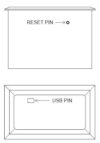
NORV AGENT 2-BC2 has a mini USB port for serial connection with the SoC for programming. Any ESP32 supported
A programming IDE can be used to program the controller. Follow this Guide to programming NORVI ESP32-based
Controllers with the Arduino IDE.
SoC: ESP32-WROOM32
Programming Port: USB UART
Wiring #
Wiring Digital Inputs and Analog Input #
The digital inputs of NORV AGENT 2-BC2 can be configured as both sink and source connections. The inverse of the
The polar digital input should be supplied to the common terminal.
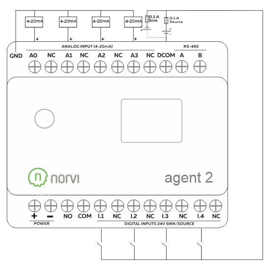
Digital Input #
Programming Digital Inputs #
Reading the relevant GPIO of the ESP32 gives the value of the Digital Input. When the inputs are off, the GPIO
goes HIGH, and when the input is in the ON stage, GPIO goes LOW. Refer to the GPIO allocation table in the Datasheet
the digital input GPIO.
void setup() {
  // put your setup code here, to run once:
  pinMode(13, INPUT);
  Serial.begin(9600);
}
void loop() {
  // put your main code here, to run repeatedly:
  int i1State = digitalRead(13);
  Serial.print("I1: ");
  Serial.println(i1State);
  delay(1000); // Adjust the delay as needed
}
4 – 20 mA Analog Input #
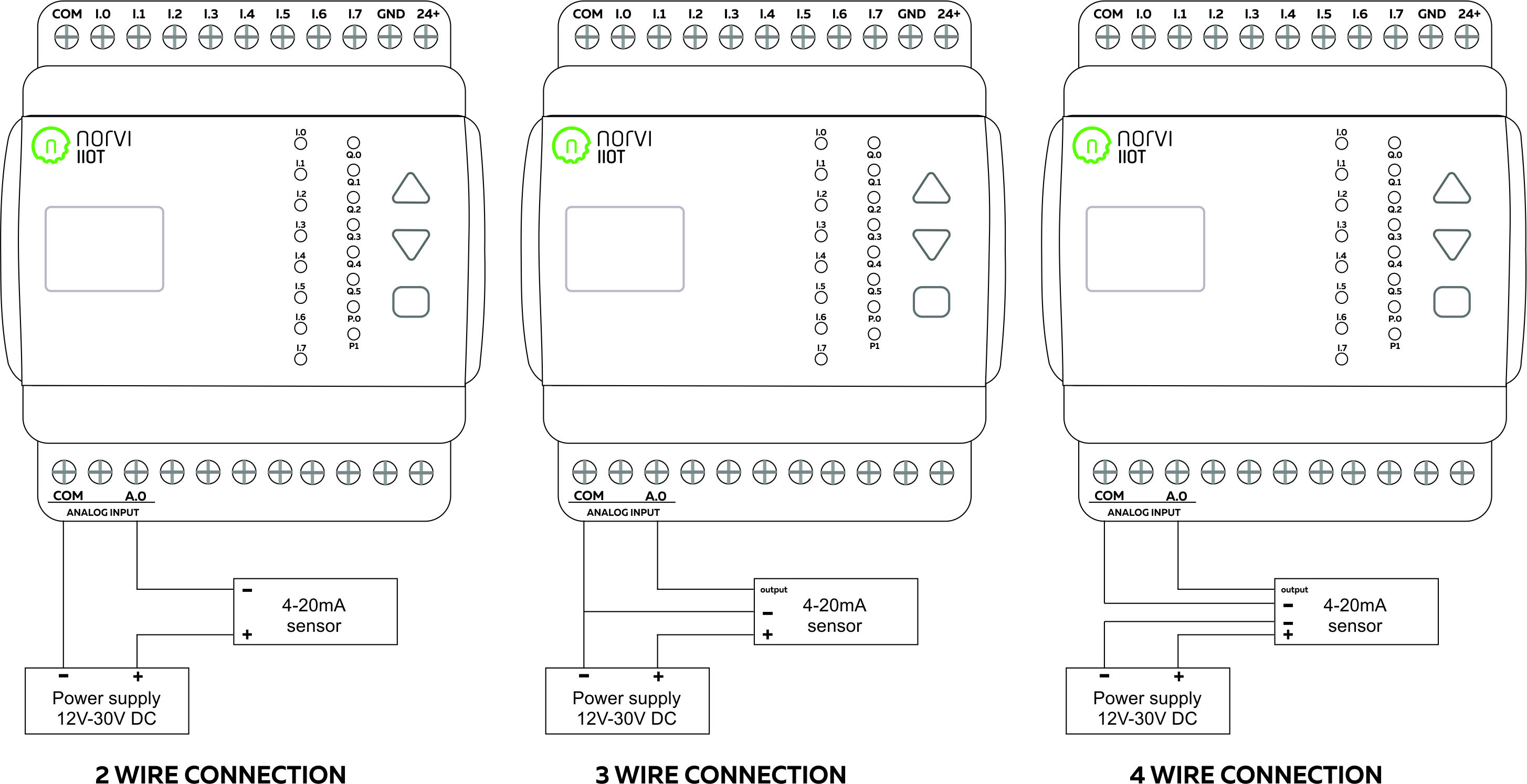
Reading Analog Input #
Reading the relevant I2C address of the ADC gives the value of the Analog Input.
Programming Analog Inputs #
#include <Wire.h>
#include <Adafruit_ADS1X15.h>
Adafruit_ADS1115 ads1; // Use this for the 16-bit version
String adcString[8];

void setup() {
  Wire.begin(21, 22);
  ads1.begin(0x49);
  ads1.setGain(GAIN_ONE);
  Serial.begin(115200);
}

void loop() { // put your main code here, to run repeatedly:
  adcString[0] = String(ads1.readADC_SingleEnded(0));
  adcString[1] = String(ads1.readADC_SingleEnded(1));
  adcString[2] = String(ads1.readADC_SingleEnded(2));
  adcString[3] = String(ads1.readADC_SingleEnded(3));
  Serial.print("A0: ");
  Serial.println(adcString[0]);
  Serial.print("A1: ");
  Serial.println(adcString[1]);
  Serial.print("A2: ");
  Serial.println(adcString[2]);
  Serial.print("A3: ");
  Serial.println(adcString[3]);
  delay(1000);
}
RS-485 Communication #
RS-485 Wiring #
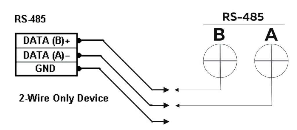
| Driver | MAX485 | ||
| UART RX | GPIO3 | ||
| UART TX | GPIO1 | ||
| Flow Control | GPIO2 |
Programming RS-485 #
The UART Connections of RS-485 of NORV AGENT 2-BC2 series are shared with the UART connections of USB
Serial.
#include <SPI.h>
#define RS485_RX 3
#define RS485_TX 2
#define RS485_FC 4

void setup() {
  Serial.begin(115200);
  Serial1.begin(9600, SERIAL_8N1, RS485_RX, RS485_TX);
  pinMode(RS485_FC, OUTPUT);
  digitalWrite(RS485_FC, HIGH); // RS-485
}

void loop() {
  // Your RS-485 communication code here
  Serial1.println("Hello RS-485");
  delay(1000);
}
Built-in OLED Display #
| Display driver | SSD1306 | ||
| Communication | I2C | ||
| Module Address | 0x3C | ||
| Resolution | 128 x 64 |
Refer to the GPIO allocation table in the datasheet for the I2C GPIO of the OLED Display. Library
The supported Adafruit_SSD0306 Library is required to initialize I2C on correct pins
Programming OLED Display #
#include "SSD1306.h" // alias for `#include "SSD1306Wire.h"`
SSD1306 display(0x3C, 21, 22);
String adcString[8];
String buttonString;

void setup() {
  display.init();
  display.flipScreenVertically();
  display.setFont(ArialMT_Plain_10);
  display.drawString(0, 0, "Hello World");
  display.display();
  Serial.begin(115200);
}

void loop() { // Your OLED display-related code here
  display.clear();
  display.drawString(0, 0, "A0: ");
  display.drawString(20, 0, adcString[0]);
  display.drawString(70, 0, "A1: ");
  display.drawString(90, 0, adcString[1]);
  display.drawString(0, 10, "A2: ");
  display.drawString(20, 10, adcString[2]);
  display.drawString(70, 10, "A3: ");
  display.drawString(90, 10, adcString[3]);
  adcString[0] = String(digitalRead(13));
  adcString[1] = String(digitalRead(14));
  adcString[2] = String(digitalRead(27));
  adcString[3] = String(digitalRead(26));
  buttonString = String(digitalRead(4));
  display.drawString(0, 20, "D1: ");
  display.drawString(20, 20, adcString[0]);
  display.drawString(70, 20, "D2: ");
  display.drawString(90, 20, adcString[1]);
  display.drawString(0, 30, "D3: ");
  display.drawString(20, 30, adcString[2]);
  display.drawString(70, 30, "D4: ");
  display.drawString(90, 30, adcString[3]);
  display.drawString(0, 40, "Button: ");
  display.drawString(40, 40, buttonString);
  display.display();
  delay(1000);
}
Built-in Buttons #
| Read mode | ADC (Analog to Digital Conversion) |
| Analog IO | GPIO4 |
Programming Buttons #
#include <Wire.h>
String buttonString;

void setup() {
  pinMode(4, INPUT); // Front panel push button switch
  Serial.begin(115200);
}

void loop() {
  // put your main code here, to run repeatedly:
  int buttonState = digitalRead(4);
  buttonString = String(buttonState);
  Serial.print("Button: ");
  Serial.println(buttonString);
  delay(1000); // Adjust the delay as needed
}
USB and Reset #