
What is NORVI X?
NORVI X is a modular industrial IoT controller built around the ESP32-S3 processor, designed to mount directly on a standard DIN rail inside a control panel. Rather than a single fixed-I/O device, NORVI X uses a CPU-plus-expansion architecture: a CPU module handles processing, display, and connectivity, while a range of expansion modules attach alongside it to add the specific inputs and outputs your application needs.
You start with a single CPU module and snap on only the expansion modules required for digital I/O, analog I/O, relay outputs, RTD sensors, and more, scaling up to 200 I/O points on one controller. Modules connect over a shared bus and are hot-swappable, so adding or changing I/O later doesn’t mean rewiring the panel.
Every CPU module includes Wi-Fi, Bluetooth, Ethernet, RS-485, a touchscreen display, a hardware real-time clock, and a microSD card slot for local data logging and buffering, as standard, with optional 4G LTE variants for cellular deployments. It’s programmed using familiar open tools Arduino IDE, ESP-IDF, or MicroPython (PlatformIO is also compatible via the same Arduino/ESP-IDF frameworks) and connects natively to cloud platforms via MQTT and HTTP.
NORVI X is built for machine builders, systems integrators, and OEMs who need industrial-grade reliability with the flexibility to scale I/O and connectivity as a project grows.
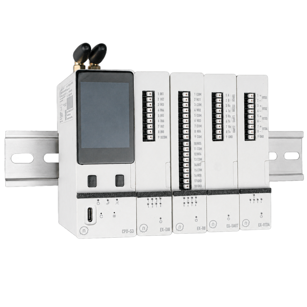
System Architecture
A NORVI X system has two building blocks:
| Component | Role |
| CPU Module | The brain ESP32-S3 processor, display, and communication ports. You pick one CPU module per controller. |
| Expansion Modules | Add I/O capability (digital in/out, analog, relay outputs, RTD, etc.). Connect multiple modules to one CPU via I²C and direct GPIO access. |
Choosing a CPU Module
All three CPU variants include the same baseline hardware: ESP32-S3-WROOM-1U-N16R2 dual-core processor, Wi-Fi 802.11 b/g/n + Bluetooth 5.0 BLE, Ethernet (RJ45), built-in RS-485, a TFT SPI touchscreen display, and a hardware real-time clock. They support up to 200 I/O points via expansion.
| Model | Best For | Adds |
|---|---|---|
| NORVI X-CPU-ESPS3-X1 | Local/Wi-Fi & wired networks | – |
| NORVI X-CPU-ESPS3-X2 | IoT-grade cellular deployments | SIMCOM A7672X (2G/4G) modem |
| NORVI X-CPU-ESPS3-X3 | High-bandwidth remote sites | Quectel EC25 (high-speed 4G LTE) modem |
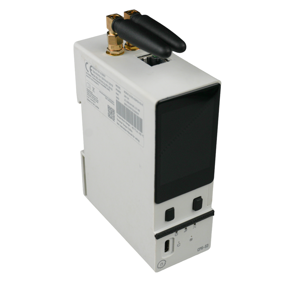
More details about NORVI CPUs – Click here
(document : NORVI X CPU Types: X1 vs X2 vs X3 Tutorial – TX02)
Quick Decision Guide
| Your Situation | Choose | Why |
|---|---|---|
| Site already has Wi-Fi or Ethernet | X1 | No cellular needed |
| Remote site, only light data (status pings, sensor readings) | X2 | IoT-grade 2G/4G modem, most cost-efficient cellular option |
| Remote site, heavy data (video, frequent large payloads) | X3 | High-speed 4G LTE for bandwidth-hungry applications |
Hardware Deep Dive
At the heart of the CPU module is an ESP32-S3-WROOM-1U-N16R2, providing 16 MB of flash, 512 KB of SRAM, and 2 MB of Quad SPI PSRAM – enough to run secure cloud connectivity (MQTTS, MQTT over TLS) and local data logging alongside your control logic without running out of memory.
Note on the N16R8 variant: A custom build with 8 MB of Octal SPI PSRAM (instead of Quad SPI) is available on request. This switch uses GPIO pins 35–37 for the Octal SPI interface, which means the N16R8 variant drops support for the X-Q4 expansion module and a few standard GPIOs. Unless your application specifically needs the extra PSRAM, the standard N16R2 is the recommended choice.
Display & Local Interface
A 2.0″ TFT touchscreen (240×320, ST7789 driver) provides on-device monitoring and configuration, alongside two physical buttons and RUN, ERROR and POWER status LEDs on the front face. A USB interface supports programming and debugging, while the microSD card slot enables local data logging and buffering. X2 and X3 variants also include a SIM card slot for cellular connectivity.
Communications
The built-in RS-485 port operates in half-duplex mode with automatic direction control, so DE/RE pin management is handled in hardware. It provides a standard serial interface for communication with Modbus RTU devices.
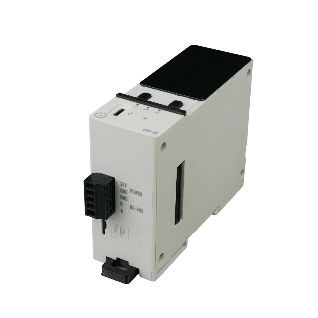
Physical Specifications
| Spec | Value |
|---|---|
| Dimensions | 81 × 104 × 37.5 mm |
| Mounting | Standard DIN rail |
| Wiring | Pluggable connector (bottom) |
| Ingress protection | IP20 |
| Power | 24V DC, ~400 mA (a 1A/24V supply is sufficient) |
Expansion Port
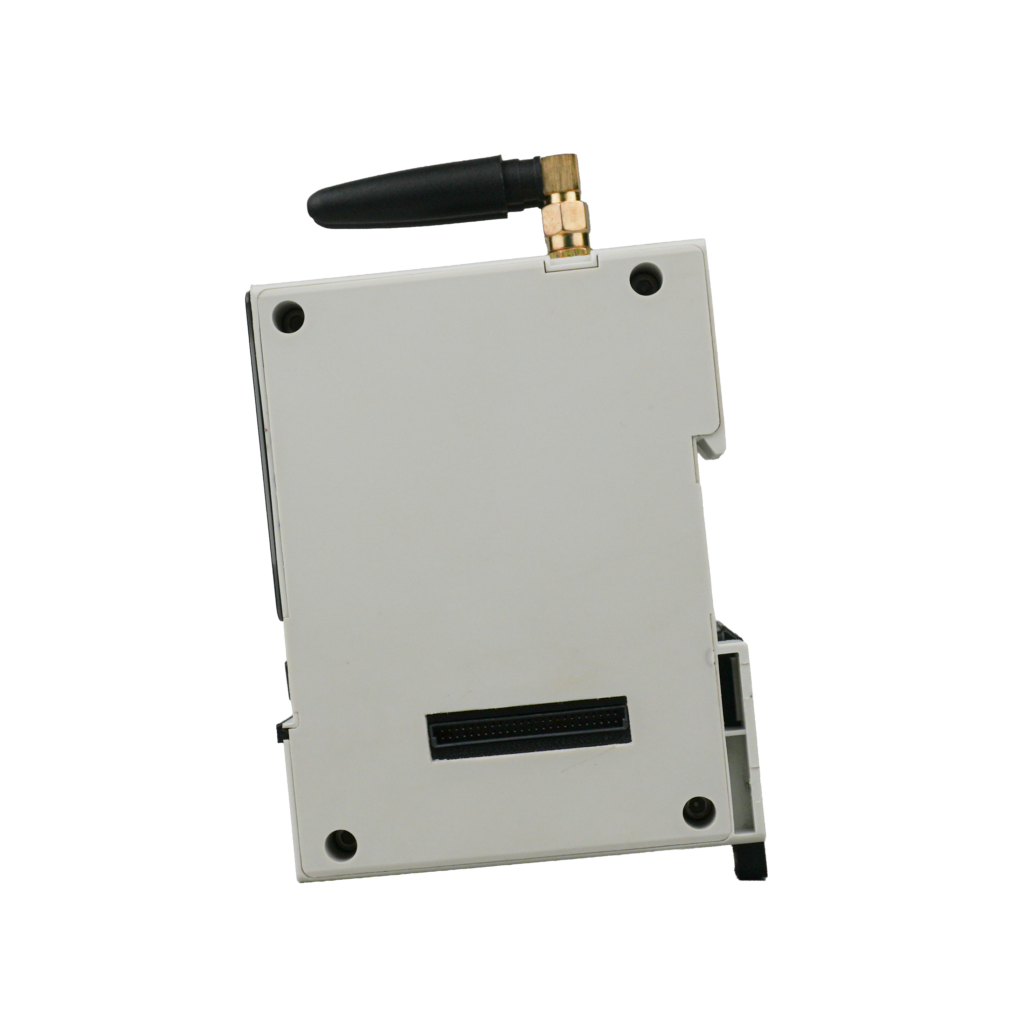
A 50-pin connector on the side of the CPU module ties the whole modular system together. It carries SPI, I²C, UART, USB, and RS-485 lines, plus 5V/24V/GND power, and dedicated chip-select lines via an onboard PCA9539 I²C expander. This is what enables hot-swapping – each module is addressed individually rather than hard-wired, so I/O can be added or changed without touching the rest of the panel.
Expansion Modules
Expansion modules plug into the CPU over I²C or direct GPIO and are hot-swappable, no rewiring or panel redesign needed when adding or changing one. NORVI currently offers 15+ modules across these categories:
| Category | Examples | Use Case |
|---|---|---|
| Digital Input | X-DI4 (GPIO), X-DI8 / X-DI16 (I²C) – 12–24V DC | Switches, pushbuttons, proximity sensors, pulse counting |
| Relay Output | X-R4, X-R8 (I²C, 5A relay) | Switching AC/DC loads – motors, HVAC, lighting |
| Transistor Output | X-Q4 (GPIO), X-Q8 / X-Q16 (I²C) – 0.5A/ch | Solenoids, steppers, PLC-style digital control |
| Analog Input | X-AV4 0–10V (I²C, 16-bit ADC), X-AI4 4–20mA (I²C, 16-bit ADC) | Sensors, transducers, process transmitters |
| Digital/AC Input | X-DA8 (I²C) – 110/230V AC | Mains-voltage status monitoring – motor/contactor state, AC power presence, lighting circuits |
| Analog Output | X-AQ4 0–10V / 4–20mA (I²C) | VFDs, proportional valves, actuators |
| Sensor | X-RTD4 (Pt100/Pt1000) | X-RTD4 (Pt100/Pt1000) Precision temperature measurement |
| Comms | X-UART-IO – RS-485 / RS-232 / UART | Legacy serial device integration |
Programming the NORVI X
- Supported environments: Arduino IDE, ESP-IDF, or MicroPython
- Upload code via the USB-C port on the CPU module
- OTA (over-the-air) firmware updates are supported, so deployed units don’t require a site visit to update
- Sample codes are available on the NORVI GitHub repository
Connectivity & Cloud Integration
- Protocols: Modbus RTU (via RS-485), Modbus TCP (via Ethernet), MQTT / MQTTS, HTTPS, UDP
- Connects natively to AWS IoT, Azure IoT Hub, Google Cloud, or a custom broker no separate gateway hardware required
Read more about: ATV320 VFD control with NORVI CPU-ESPS3-X2
Quick Start Checklist
- Choose your CPU module (X1 / X2 / X3) based on connectivity needs
- Select and attach the expansion modules your application requires
Note: When selecting expansion modules, refer to the NORVI X Mixing Guide to ensure the selected modules are compatible. - Mount the assembled unit on a TH35 DIN rail
- Wire the 24V DC power supply
- Connect via USB-C and install your firmware (Arduino IDE / ESP-IDF / MicroPython)
- Configure network settings (Wi-Fi, Ethernet, or cellular) via the touchscreen or code
- Verify I/O and connectivity, then deploy