Winding temperature
Monitor one or more phase windings using installed Pt100 or Pt1000 sensors where the transformer design provides them.

Transformer Condition Monitoring
Transformer temperature monitoring for dry-type and cast resin transformers helps operators track winding and ambient heat continuously. NORVI X and the 4-channel X-RTD4 read Pt100 or Pt1000 sensors directly. In addition, the platform can provide local display, configurable alarms, timestamped logging, SCADA integration and cloud connectivity.
Why monitor temperature
Transformer temperature is a direct indicator of thermal loading, cooling performance and insulation stress. Therefore, continuous monitoring gives operators a clear view of winding and sensor temperatures between scheduled inspections.
Manufacturers commonly embed temperature sensors in or close to dry-type and cast resin transformer windings. The controller then reads each sensor, compares the value with approved limits, records trends and sends alarms when a configured condition occurs.
Important: Alarm, fan and trip temperatures vary between transformer designs. Therefore, commission every setpoint from the transformer manufacturer's documentation and the project protection philosophy. The monitoring system should apply those approved limits rather than create new protection values.
Monitor one or more phase windings using installed Pt100 or Pt1000 sensors where the transformer design provides them.
Track enclosure or room temperature to distinguish a transformer heating event from a wider ventilation or environmental problem.
Combine temperature data with fan, contactor or digital status inputs when the project needs confirmation that forced cooling has started.
Use recorded temperature history to identify rising baselines, load-related peaks, ventilation issues and recurring thermal events.
Exact application
Dry-type transformer temperature monitoring focuses primarily on winding temperature and the surrounding air path because the transformer does not use a liquid insulation and cooling system. Embedded temperature sensors provide direct feedback from the active part of the transformer, while an additional ambient sensor can help explain why temperatures are rising.
A practical monitoring architecture uses the NORVI X-RTD4 to read up to four Pt100 or Pt1000 channels. For example, you can assign three channels to phase winding sensors and use the fourth for ambient, core or another transformer-provided RTD point. Review the NORVI X-RTD4 datasheet for the current terminal layout, supported RTD types and module specifications.
IEC 60076-11 covers dry-type power transformers within its stated scope, while IEEE C57.134 provides guidance for determining winding hottest-spot temperature in dry-type transformers. Monitoring data can support maintenance and condition assessment, but the transformer manufacturer's approved thermal limits remain the commissioning reference.
Exact application
Cast resin transformer temperature monitoring uses winding sensors to supervise thermal loading and generate alarm or trip signals at approved limits. In particular, Pt100 RTDs suit applications that need a continuous temperature value rather than only a fixed thermistor response.
For a three-phase cast resin transformer, a common design uses one winding temperature point per phase. A fourth channel can monitor ambient temperature or another manufacturer-provided point. NORVI X-RTD4 acquires all four channels, while the NORVI X controller processes the values locally.
Some cast resin transformer manufacturers use separate temperature stages for fan control, alarm and trip. These values differ by transformer model and thermal class. For example, manufacturer documentation for some Class F designs shows staged values such as fan control below alarm, followed by a higher alarm and trip level. Use the exact values supplied for the installed transformer.
Assign RTD channels to L1, L2 and L3 winding sensors and display all three temperatures together for fast phase comparison.
Use configurable logic to request forced-air cooling when the transformer manufacturer specifies a fan stage and confirm fan status through additional I/O if required.
Create separate warning and critical states, add delay or hysteresis where approved, and forward the event to the local HMI, SCADA or cloud platform.
Remote monitoring
A transformer temperature monitoring system should keep critical alarm logic local while adding remote visibility. NORVI X reads RTD temperatures at the panel and processes the alarm logic locally. At the same time, it can send selected data to remote dashboards for alerts, trend analysis and maintenance reporting.
Use Ethernet or Wi-Fi where a site network already exists. However, remote substations may need the cellular connectivity available with NORVI X2 or X3. In addition, MQTT and HTTP support cloud publishing, while RS-485 Modbus RTU and Ethernet support SCADA or BMS integration. See the NORVI X industrial IoT controller platform for CPU, communication and expansion options.
Keep temperature acquisition and critical alarm logic on the controller so basic monitoring does not depend on cloud availability.
Publish live values, daily maximums, alarm state and communication health to the platform used by your operations team.
Send alarms through the connected platform, email, SMS workflow or another integration selected by the system integrator.
Store timestamped values for thermal trend review, maintenance planning and comparison against load or ambient conditions.
Installation reference
The X-RTD4 provides four independent RTD channels. The current NORVI datasheet identifies paired positive and negative terminals for channels 1 to 4 plus a ground terminal. Confirm the actual transformer sensor wiring and RTD type before energizing the monitoring panel. For controller setup and expansion installation, follow the NORVI X getting started guide.
RTD type selection: The current X-RTD4 datasheet provides a hardware selection for Pt100 and Pt1000 operation. Set the module for the sensor type installed in the transformer. Do not assume the sensor type from wire colour alone. Check the transformer drawings, terminal schedule or sensor documentation.
Protection philosophy
Use staged alarms to create a clear response path. However, always commission the actual temperatures from the transformer manufacturer. The table below supports project planning and firmware structure, but it does not replace the transformer's approved protection settings.
| Stage | Purpose | Temperature value | Recommended system action |
|---|---|---|---|
| Normal | Healthy operating range | Below the transformer manufacturer's first intervention threshold | Display and log temperature. Track phase imbalance and long-term trend. |
| Fan / Cooling | Start forced ventilation where fitted | Manufacturer-defined | Request fan start, log the event and optionally verify fan run status. |
| High Alarm | Warn operators before a critical thermal condition | Manufacturer-defined | Raise local and remote alarm, record peak temperature and notify operations. |
| High-High / Trip | Critical overtemperature protection | Manufacturer-defined | Issue the approved trip request or interlock signal through the engineered protection system. |
Manufacturer example only: documentation for one Class F cast resin transformer family specifies 130 °C for fan control, 140 °C for the first alarm and 150 °C for the second alarm. Therefore, use this example only when the installed transformer's manufacturer specifies the same settings.
Standards and records
A transformer monitoring controller does not replace transformer certification or a dedicated protection relay. Instead, it acquires temperature data, applies approved project logic, provides alarms and preserves useful operating records.
IEC 60076-11 applies to dry-type power transformers within the standard's stated scope. IEC 60076-12 addresses loading guidance and insulation ageing as a function of operating temperature, time and load. IEEE C57.134 provides methodologies for determining winding hottest-spot temperature in dry-type distribution and power transformers.
For projects that require audit trails, program NORVI X to store timestamped temperature readings, alarm transitions, acknowledgement events and communication status. Then, forward those records to the plant historian, SCADA system or cloud platform used by the operator.
Compliance scope: Reference the transformer manufacturer's manual, the project protection study and the standards applicable to the transformer itself. Do not describe a monitoring controller as making the transformer IEC or IEEE compliant.
Recommended architecture
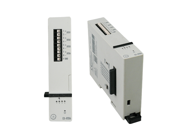
NORVI X-RTD4 adds four RTD channels to the modular NORVI X platform. As a result, one module can collect winding and ambient temperature points for a compact transformer monitoring panel.
Choose NORVI X1 where the transformer panel already has Ethernet or Wi-Fi access. It combines the ESP32-S3 controller, RS-485, Ethernet, local TFT display and expansion support. For a wider overview of NORVI's controller architecture, see the ESP32 PLC platform.
View NORVI XUse where cloud-based transformer monitoring needs a cellular path in addition to local Ethernet, Wi-Fi and RS-485 connectivity.
Compare CPU OptionsAdd four Pt100 or Pt1000 RTD channels for winding, ambient or other transformer-provided temperature points.
Open RTD4 DatasheetEngineering resources
Use the current NORVI documentation library as the source of truth for terminal assignments, module selection and software implementation.
Related NORVI resources: X-RTD4 datasheet, NORVI X controller, ESP32 PLC overview, NORVI X getting started, and the NORVI documentation library.
FAQs
Can't find what you're looking for? Our team is available for a free technical consultation.
Use sensors that the transformer manufacturer provides or approves. Then, monitor the winding phases continuously and configure fan, alarm and trip stages from the transformer documentation. NORVI X with X-RTD4 can read up to four Pt100 or Pt1000 channels and forward the data to local or remote systems.
Yes. The NORVI X-RTD4 provides four independent RTD inputs and supports Pt100 and Pt1000 selection. A typical three-phase application can use three channels for winding sensors and a fourth for ambient or another transformer-provided RTD point.
There is no single alarm temperature that is correct for every transformer. Use the transformer manufacturer's specified fan, alarm and trip values and coordinate them with the project's protection philosophy. Thermal class, transformer construction, cooling method and sensor location all matter.
Yes. NORVI X can publish temperature data through MQTT or HTTP over Ethernet, Wi-Fi or cellular connectivity, depending on the selected CPU model. Critical local monitoring logic should remain on the controller so basic alarm behaviour does not depend on the cloud connection.
Yes. NORVI X includes RS-485 and Ethernet connectivity for Modbus-based SCADA workflows. In addition, the application firmware defines the register map and control behaviour for the project.
No. Monitoring can support temperature supervision, records and engineered alarm logic, but compliance applies to the transformer and overall installation against the relevant requirements. The transformer manufacturer's documentation and applicable standards remain the reference.
Tell us the transformer type, sensor type, number of RTD points, required alarm stages and whether you need Ethernet, Wi-Fi, SCADA or cellular cloud connectivity. We can help you select the NORVI X CPU and expansion configuration.
Due to a surge in global demand, our production queue is at full capacity. We will not accelerate production at the expense of quality - every device undergoes full CE / EMC compliance, regardless of order volume.
| Order Quantity | Lead Time | Notes |
|---|---|---|
| Under 10 units | 2-3 wks | Standard processing |
| 10 - 100 units | 4-5 wks | Mid-volume batch |
| Above 100 units | 6+ wks | Contact us for slot |