
Introduction #
This tutorial explains how to control and monitor a Schneider Electric ATV320 variable frequency drive (VFD) using a NORVI CPU-ESPS3-X2 industrial controller over Modbus RTU, and how to publish the resulting motor-health data and fault history to a ThingsBoard cloud dashboard.
The controller runs the drive locally: start, stop, reverse and frequency selection are all handled by the NORVI CPU-ESPS3-X2, which independently reports live status to the cloud so the drive can be monitored and operated remotely from a desktop or mobile dashboard.
System Architecture #

What You Will Need #
- An ATV320 VFD wired to its motor and mains supply by a qualified technician.
- A NORVI CPU-ESPS3-X2 controller with the ATV320_NORVI_Modbus_Control firmware.
- An RS-485 twisted-pair connection between the NORVI CPU-ESPS3-X2 and the ATV320 Modbus terminals.
- An active data SIM card fitted to the NORVI CPU-ESPS3-X2’s on-board modem, for the ThingsBoard cloud link.
- A ThingsBoard account (cloud or self-hosted) with a device access token.
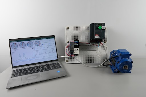
Hardware and Wiring #
Field wiring for this project is minimal: the NORVI CPU-ESPS3-X2 has an on-board cellular modem, so no separate modem wiring is needed. The only inter-device connection required is the RS-485 link between the NORVI’s side connector and the ATV320’s Modbus terminals, plus a 24 VDC supply to power the NORVI module itself.
RS-485 and Power Wiring #
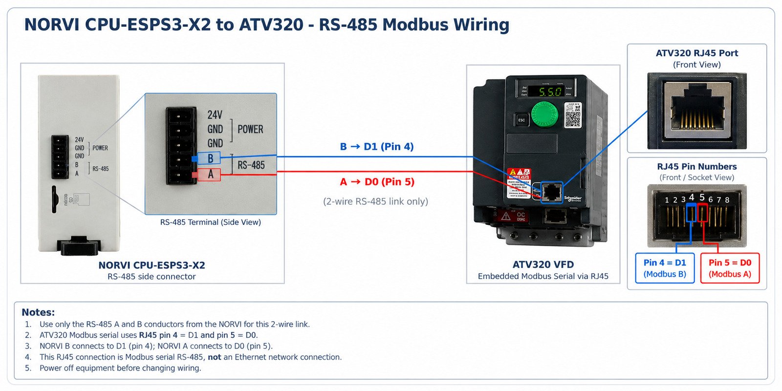
Caution: A and B terminal labels differ between manufacturers. If the link does not respond, verify the ATV320 terminal documentation and swap A/B only with power removed. Use twisted-pair cable, route it away from motor output wiring, and terminate the bus at its physical ends where required.
Software Setup #
The firmware is written in the Arduino framework for the ESP32-S3 and runs two FreeRTOS tasks in parallel: one for real-time drive control, one for cloud telemetry. Key steps:
- Define pin configurations as per the datasheet.
- Initialize the RS-485 port (19200, 8-E-1) and the on-board cellular modem.
- Auto-detect the ATV320’s Modbus addressing offset, then start the drive-control and cloud-telemetry tasks.
- vfdTask: read buttons, write command/speed (fn 0x10), read health and ETA (fn 0x03) every 200 ms, and poll fault history every 5 s.
- gsmTask: connect to the cellular network and MQTT broker, then publish live and fault telemetry to ThingsBoard every 30 s.
- Update the TFT display and status LEDs with the latest drive state.
Please refer to the GitHub repository below for the full program:
ATV320 NORVI Modbus Control – Full Source Code
ATV320 Communication Settings #
Configure the ATV320’s integrated Modbus port to match the firmware before attempting to communicate:
| Setting | Value |
|---|---|
| Modbus address | 1 |
| Baud rate | 19200 |
| Format | 8-E-1 |
| Protocol | Modbus RTU |
| Modbus timeout | 5–10 s during commissioning |
Timeout menu path on the ATV320 keypad:
CONF > FULL > COM- > MD1- > ttoNote: The firmware uses slave ID 1 at 19200 baud. Keep the drive’s Modbus timeout longer than any delay that cellular/GSM activity could introduce, so a temporarily busy modem cannot trip a communication-loss fault.
VFD Parameter Setup from the Keypad #
Before the NORVI controller can run the drive, the ATV320 itself must be configured from its integrated keypad/display. This section lists the parameters a technician sets on the drive, in the order they are normally configured. Screen names below follow the ATV320 graphic/integrated display menu structure.
Factory Reset (recommended before first commissioning) #
On a drive that has been used before, start from a known state:
CONF > FULL > FCS- > FCS = InI (initialize to factory settings)Caution: A factory reset erases all existing parameters. Only perform this on a drive being newly commissioned, and record any settings you need to keep beforehand.
Motor Nameplate Parameters (drC- menu) #
Enter the values printed on the motor nameplate. These allow the drive to compute correct current limits, torque control and autotuning.
| Parameter | Code | Description |
|---|---|---|
| Motor standard | bFr | 50 Hz (Europe/Asia) or 60 Hz (North America) |
| Rated motor power | nPr | Nameplate power (kW or HP) |
| Rated motor voltage | UnS | Nameplate voltage (V) |
| Rated motor current | nCr | Nameplate full-load current (A) |
| Rated motor frequency | FrS | Nameplate frequency (Hz) |
| Rated motor speed | nSP | Nameplate speed (RPM) |
| Motor thermal current | ItH | Normally set equal to nCr |
Autotuning (drC- menu) #
Run autotuning with the motor stationary and safely secured, so the drive can measure winding resistance and improve control accuracy:
CONF > FULL > drC- > TUN = YESNote: Autotuning briefly energizes the motor without rotating the shaft. Confirm the motor is mechanically free to do this safely (no load engaged that would be damaged by a brief current pulse) before starting.
Command and Reference Channel (CtI- menu) #
This is the key step that hands run/stop and speed-reference control to the Modbus network rather than the keypad or terminal I/O:
| Parameter | Code | Setting for this project |
|---|---|---|
| Command channel 1 | Cd1 | ntw (network / Modbus) |
| Reference channel 1 | Fr1 | ntw (network / Modbus) |
| Combined reference/command | CHCF | SIM (simple, single channel) unless a second channel is used |
| 2-wire / 3-wire control | tCC | Not used when Cd1 = ntw; drive is fully network-controlled |
Caution: If Cd1 / Fr1 are left on their default (terminal I/O) setting, the drive will ignore Modbus run/stop and speed commands sent by the NORVI controller. This is the single most common reason a new installation reads telemetry correctly but does not respond to commands.
Ramp Times and Speed Limits (FUn- menu) #
| Parameter | Code | Typical Purpose |
|---|---|---|
| Acceleration ramp | ACC | Time to go from 0 to rated frequency |
| Deceleration ramp | dEC | Time to go from rated frequency to 0 |
| Low speed limit | LSP | Minimum output frequency |
| High speed limit | HSP | Maximum output frequency – must not exceed motor/mechanical rating |
Set HSP to comfortably cover the highest frequency the firmware will request (the firmware’s push-button range is 45.0–110.0 Hz before the REF_GAIN scaling described in Section 7.1 is applied) – verify the resulting on-wire value against HSP so the drive never clips or rejects the reference.
Communication Menu and Scanner #
Set the Modbus port parameters as in Section 4, then configure the communication scanner (ICS-) exactly as described in Section 6 so that nM1–nM4 map to OPR, RFRD, OTR and LCR.
Save and Verify #
- Save parameters if the keypad requires an explicit save/confirm step.
- Cycle power or re-enter the monitoring menu and confirm nameplate values were retained.
- With the NORVI controller powered and RS-485 connected, confirm the drive accepts a stop command, then a low-speed forward command, before running at full commanded speed.
Communication Scanner Setup #
The ATV320’s Modbus scanner (ICS) maps drive parameters onto fixed registers that the controller reads in a single request. Configure it from:
CONF > FULL > COM- > ICS-| Scanner | Parameter | Decimal | Hex | NORVI Register |
|---|---|---|---|---|
| nMA1 | OPR – motor power | 3211 | 0C8B | nM1 / 12741 |
| nMA2 | RFRD – actual frequency | 8604 | 219C | nM2 / 12742 |
| nMA3 | OTR – motor torque | 3205 | 0C85 | nM3 / 12743 |
| nMA4 | LCR – motor current | 3204 | 0C84 | nM4 / 12744 |
If the keypad only accepts hexadecimal entry, use:
nMA1 = 0C8BnMA2 = 219CnMA3 = 0C85nMA4 = 0C84Caution: Changing these scanner entries overwrites any previous scanner assignment on the drive. The firmware assumes nM1–nM4 map to OPR, RFRD, OTR and LCR in that exact order – reassigning them without updating the code will corrupt the telemetry.
The drive status word (ETA) is read separately from the scanner, at decimal 3201 (hex 0C81).
Modbus Register Map #
Control Writes (Function 0x10) #
The firmware writes two consecutive holding registers, starting at 12761, using function code 0x10 (Write Multiple Registers):
| Function | Decimal | Hex | Content |
|---|---|---|---|
| Scanner output 1 / CMD | 12761 | 31D9 | Command word |
| Scanner output 2 / LFRD | 12762 | 31DA | Speed reference |
| Command | Value | ||
| Stop | 0x0000 | ||
| Forward run | 0x0001 | ||
| Reverse run | 0x0004 | ||
Caution: The firmware applies REF_GAIN = 3.0: the speed reference is multiplied by 3 before it is written to the drive, and feedback is divided by 3 for display and telemetry. This scaling is installation-specific and must be re-validated for each site – for example, a 50 Hz operator setpoint is transmitted on the wire as 150.
Live Health Reads (Function 0x03) #
Four consecutive registers are read in one request:
start register = 12741quantity = 4| Register | Meaning | Telemetry Key |
|---|---|---|
| 12741 / nM1 | OPR – motor power | opr |
| 12742 / nM2 | RFRD – actual frequency | af |
| 12743 / nM3 | OTR – motor torque | otr |
| 12744 / nM4 | LCR – motor current | mc |
Note: Reported scaling: OPR in 1% steps, RFRD in 0.1 Hz units, OTR in 0.1% units and LCR in 0.1 A units. Always confirm the returned scaling against the VFD keypad display before using the values for maintenance decisions.
ETA Status Word #
| Parameter | Decimal | Hex |
|---|---|---|
| ETA status word | 3201 | 0C81 |
Published status telemetry fields derived from ETA: sw (raw status word), fault, warn and sod (state of drive).
Fault History Addresses #
Fault-related addresses are taken from the ATV320 communication parameters reference (NVE41316).
| Parameter | Meaning | Decimal | Hex |
|---|---|---|---|
| LFT | Last fault occurred | 7121 | 1BD1 |
| FNB | Fault counter | 7393 | 1CE1 |
| DP0 | Fault code – last/actual record | 7200 | 1C20 |
| DP1 | Fault code n-1 | 7201 | 1C21 |
| DP2 | Fault code n-2 | 7202 | 1C22 |
| DP3 | Fault code n-3 | 7203 | 1C23 |
| DP4 | Fault code n-4 | 7204 | 1C24 |
| DP5 | Fault code n-5 | 7205 | 1C25 |
| DP6 | Fault code n-6 | 7206 | 1C26 |
| DP7 | Fault code n-7 | 7207 | 1C27 |
| DP8 | Fault code n-8 | 7208 | 1C28 |
The firmware reads LFT and FNB individually, then reads eight consecutive words starting at DP1 in a single request.
Note: Last-fault snapshot registers (drive state, ETA/ETI state, command word, current, frequency, run time, mains voltage and thermal state at the moment of the last fault) are documented in the source reference but are not yet read by the current firmware. They can be added as a future enhancement using the same read pattern.
Modbus RTU Frame Format and CRC #
Read Request (Function 0x03) #
[slave][03][register hi][register lo][quantity hi][quantity lo][CRC lo][CRC hi]Write Request (Function 0x10) #
[slave][10][start hi][start lo][quantity hi][quantity lo][byte count][data...][CRC lo][CRC hi]Every response is validated against: slave address, function code, byte count, CRC, and – for writes – the echoed write acknowledgement.
CRC-16 (Modbus) #
| Parameter | Value |
|---|---|
| Initial value | 0xFFFF |
| Polynomial | 0xA001 |
| Bit processing order | LSB-first |
| Wire byte order | CRC low byte, then CRC high byte |
This is implemented in the firmware function crc16_modbus().
Polling and Task Scheduling #
The firmware runs two FreeRTOS tasks pinned to separate cores, with the VFD task given the higher priority:
xTaskCreatePinnedToCore(vfdTask, "vfdTask", 8192, nullptr, 1, &vfdTaskHandle, 0);xTaskCreatePinnedToCore(gsmTask, "gsmTask", 12288, nullptr, 0, &gsmTaskHandle, 1);The VFD task services buttons and Modbus traffic every 200 ms; fault history is polled every 5 seconds. One VFD cycle performs:
- Read push-buttons PB1 / PB3.
- Process any pending reverse-direction transition.
- Write the command word and speed reference (function 0x10).
- Read nM1–nM4, the live health block (function 0x03).
- Read the ETA status word.
- Every 5 seconds: read LFT, FNB and DP1–DP8.
- Update LEDs, drive status and runtime metrics.
Note: Keep the ATV320’s configured Modbus timeout comfortably longer than any single operation that could momentarily delay polling – this prevents a false SLF1 (communication interruption) fault during normal cellular activity.
ThingsBoard MQTT Integration #
Connection Settings #
| Setting | Value |
|---|---|
| Host | mqtt.thingsboard.cloud |
| Port | 1883 |
| Topic | v1/devices/me/telemetry |
| Username | ThingsBoard device access token |
| AT publish sequence | CMQTTTOPIC → CMQTTPAYLOAD → CMQTTPUB |
Caution: Port 1883 is unencrypted MQTT, used here for simplicity during development. Production installations should migrate to a tested TLS flow on port 8883, and the device access token and cellular APN must be kept out of any publicly shared source.
Live Telemetry Payload #
{ "sw": 0, "af": 0.0, "opr": 0, "otr": 0, "mc": 0, "run": 0, "rev": 0, "mb": 0, "fault": 0, "warn": 0, "sod": 0, "run_s": 0, "last_run_s": 0, "starts": 0}Fault History Payload #
{ "lft": "NOF", "fnb": 0, "dp1": "NOF", "dp2": "NOF", "dp3": "NOF", "dp4": "NOF", "dp5": "NOF", "dp6": "NOF", "dp7": "NOF", "dp8": "NOF"}Fault codes are sent as compact mnemonics to minimize cellular payload size. Decode them on the ThingsBoard side using a Value Card value function or a table Cell Content Function, mapping each mnemonic to a readable description (see Section 12).
Fault Code Reference #
| Code | Meaning |
|---|---|
| NOF | No fault |
| SLF1 | Modbus communication interruption |
| USF | Supply mains undervoltage |
| ASF | Angle error |
| OCF | Overcurrent |
| OHF | Drive overheating |
| OLF | Motor overload |
| OBF | DC bus overvoltage |
| OSF | Supply mains overvoltage |
| OPF1 | Single output phase loss |
| OPF2 | Three-output-phase loss |
| PHF | Input phase loss |
| SCF1 | Motor short circuit |
| SCF3 | Ground short circuit |
| SCF4 | IGBT short circuit |
| SCF5 | Motor short circuit during IGBT sequence |
| SOF | Motor overspeed |
| TNF | Autotuning error |
| TJF | IGBT overheating |
| BLF | Brake control fault |
| BRF | Brake feedback fault |
| CNF | Fieldbus / network communication fault |
| COF | CANopen communication fault |
| SAFF | Safety function fault |
| FBE | Function block fault |
| FBES | Function block stop fault |
ThingsBoard Dashboard Design #
Build the dashboard from the telemetry keys published in Section 11. Recommended widget mapping:
| Widget Type | Suggested Keys |
|---|---|
| Latest Value / Value Card | run, rev, mb, fault, warn, sod, lft, fnb |
| Analog / Digital Gauge | af (frequency), opr (power), otr (torque), mc (current) |
| Numeric Card | run_s, last_run_s, starts |
| Table | lft, dp1 … dp8 (decoded fault history) |
| Time Series Chart | af, opr, otr, mc over time |
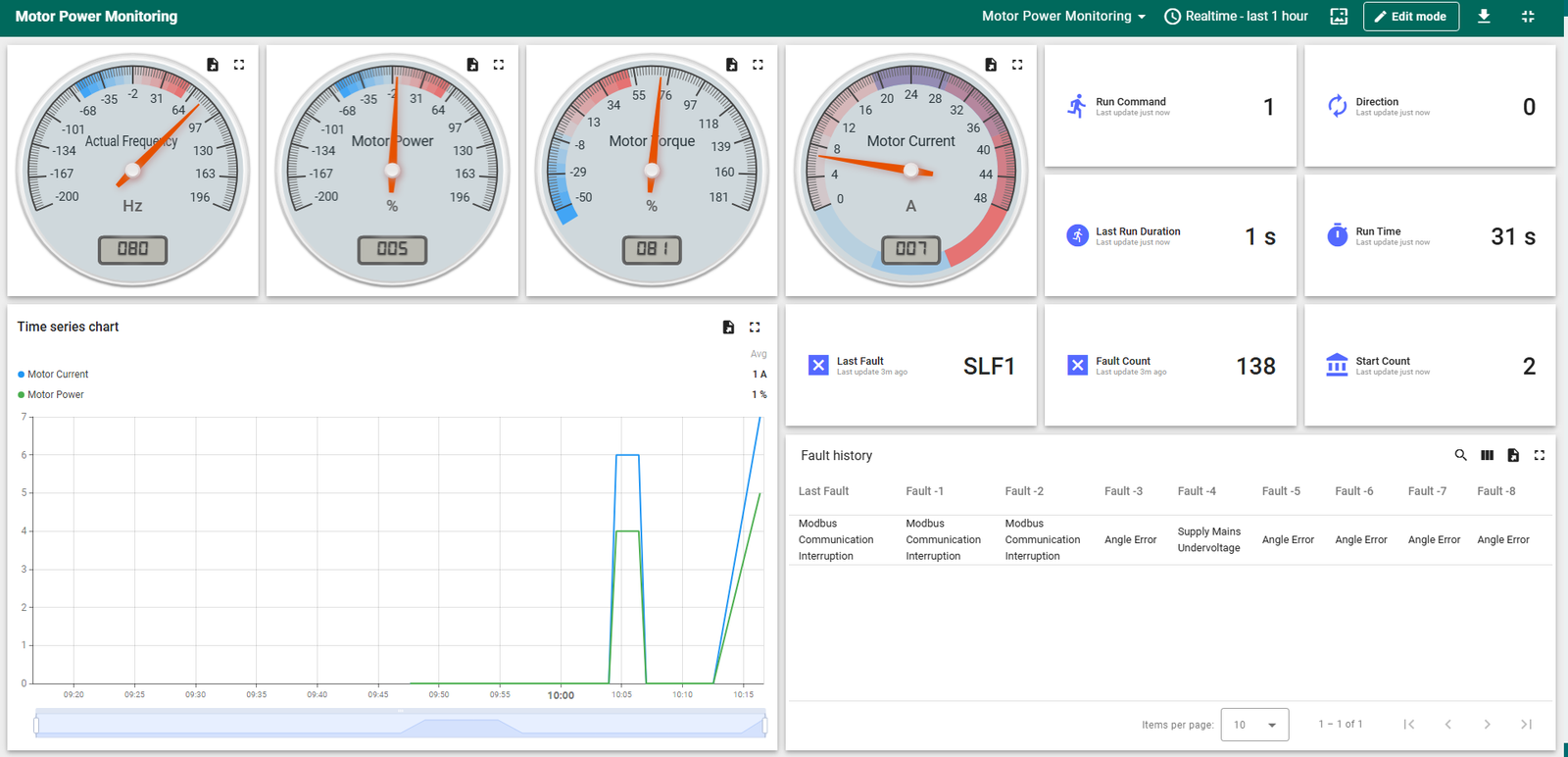
Suggested fault-history table columns:
| Key | Display Name |
|---|---|
| lft | Last Fault |
| dp1 | Fault History 1 |
| dp2 | Fault History 2 |
| dp3 | Fault History 3 |
| dp4 | Fault History 4 |
| dp5 | Fault History 5 |
| dp6 | Fault History 6 |
| dp7 | Fault History 7 |
| dp8 | Fault History 8 |
Commissioning Checklist #
- Confirm safe mechanical conditions and follow an approved VFD lock-out/tag-out procedure.
- Set the ATV320 to address 1, 19200 baud, 8-E-1 (Section 4).
- Enter motor nameplate parameters, run autotuning, and set the command/reference channel to network control (Section 5).
- Set scanner entries nMA1–nMA4 to OPR, RFRD, OTR and LCR (Section 6).
- Confirm motor wiring, supply voltage and mechanical safety are in order.
- Upload the firmware and open a serial monitor at 115200 baud.
- Confirm the log shows [VFD] Modbus ONLINE.
- Confirm nM1–nM4 update correctly in the ATV320 monitor menu.
- Confirm live telemetry is arriving in ThingsBoard.
- Confirm both MQTT publishes return +CMQTTPUB: 0,0.
- Test stop, forward, reverse and frequency changes at a safe, reduced speed.
- Confirm fault-history values read back correctly.
Troubleshooting #
Modbus Offline #
Check RS-485 A/B polarity, slave address, baud rate, 8-E-1 format, the GPIO 41 direction-control line, bus termination, cable routing, and the ATV320 Modbus timeout setting.
SLF1 – Modbus Communication Interruption #
Check the RS-485 wiring, and verify that modem/cellular operations are not delaying VFD polling beyond the configured Modbus timeout.
ASF – Angle Error #
Check motor phase wiring, motor parameter settings, autotuning status, input voltage, drive-to-motor voltage compatibility, and the installation-specific REF_GAIN behavior described in Section 7.1.
MQTT Publish Failure #
Check the APN configuration, SIM registration status, antenna connection, IP assignment, ThingsBoard access token, broker response, and payload length. Since the modem is built into the NORVI CPU-ESPS3-X2 board, weak signal or a poorly seated SIM are the most likely causes rather than external wiring. Remember the current configuration uses unencrypted MQTT on port 1883 (Section 11.1).
Zero or Missing Telemetry #
If the VFD is powered off, zero values and a NOF fault history are expected. If the VFD is powered on, check nM1–nM4 directly in the drive’s monitor menu and confirm function 0x03 requests are receiving responses.
Drive Reads Correctly but Will Not Run or Change Speed #
Telemetry arrives normally but the drive ignores stop/run/reverse and speed commands: this almost always means the command and reference channels (Cd1, Fr1) are still on the keypad or terminal I/O default instead of network control. Re-check Section 5.4.
Safety and Production Notes #
- This software must never replace an emergency-stop circuit or a certified safety system.
- Motor, drive, supply and protective devices must be verified by a qualified technician.
- Store access tokens and cellular APN credentials securely; never distribute them in shared source code.
- Runtime counters reset on ESP32S3 restart – use non-volatile storage if permanent records are required.
- Always validate current, torque and frequency scaling against the drive’s own display before using the data for maintenance decisions.