
Introduction #
Furnaces and ovens usually fail in one of two ways: they run too hot, or they heat too fast. A SCADA system gives plant-wide oversight, but the operator at the machine still needs instant, readable feedback and a clear warning the moment either limit is crossed.
This tutorial builds a complete ESP32 thermistor temperature monitor on the NORVI X-CPU-ESPS3-X1 with the NORVI X-T4 module. You connect a 10kΩ NTC thermistor, convert its resistance to °C with the Beta equation, apply a compensation offset, track the rate of rise per minute, and raise warning, over-temperature, rate-of-rise and sensor-fault alarms on the built-in TFT display. The same method suits any oven, kiln, heater or process zone that stays inside the probe’s rated range.
What you will need
- NORVI X-CPU-ESPS3-X1 controller and NORVI X-T4 module
- 24 V DC supply rated at 1 A or higher
- 10kΩ NTC thermistor (R25 = 10kΩ), 2-wire, rated for your process temperature
- USB cable and the Arduino IDE with ESP32 board support
System Architecture #
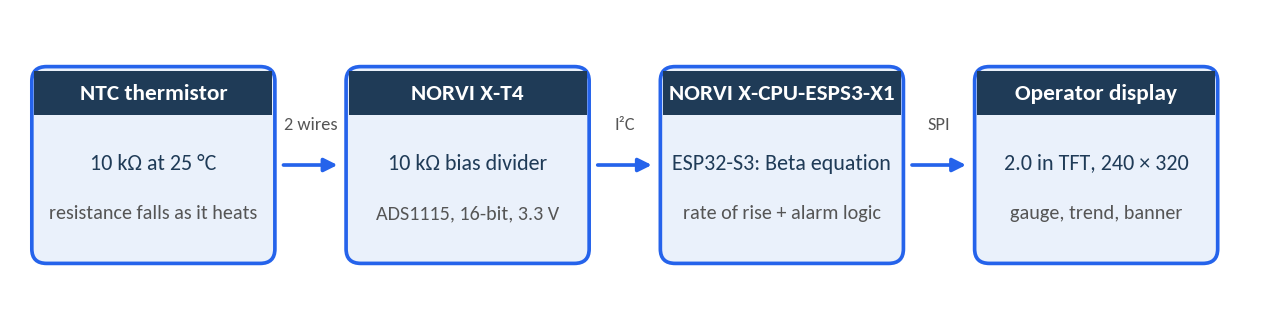
The system forms a short signal chain from the furnace probe to the operator display.
Signal flow #
- Sensing. The NTC thermistor’s resistance falls as the furnace heats up, from about 33kΩ at 0 °C to 10kΩ at 25 °C and 3.6kΩ at 50 °C.
- Conversion. The X-T4 places the thermistor in a divider with a 10kΩ bias resistor, and its 16-bit ADS1115 digitizes the divider voltage.
- Processing. The ESP32-S3 reads the ADC over I²C, averages and smooth the result, converts it to °C, and works out the rate of rise and the alarm state.
- Indication. The controller draws the value, gauge, trend and status banner on the TFT display.
Hardware components #
| Component | Role | Key details |
|---|---|---|
| NORVI X-CPU-ESPS3-X1 | Controller | ESP32-S3-WROOM-1U-N16R2 with 16 MB flash and 2 MB QSPI PSRAM; 2.0 in ST7789 TFT (240 × 320); 24 V DC supply |
| NORVI X-T4 | Thermistor input | 4 NTC channels; ADS1115 16-bit ADC (3.3 V) at I²C address 0x48 by default; powered through the expansion port |
| 10kΩ NTC thermistor | Field sensor | 2-wire, R25 = 10kΩ, B = 3892 K in this sketch (Littelfuse 103JG1K) |
Pin allocation #
| Function | GPIO | Notes |
|---|---|---|
| I²C bus (SDA / SCL) | IO8 / IO9 | Shared by the ADS1115 (0x48) and the on-board touch, I/O expander and RTC devices |
| TFT display (CS / DC / RST) | IO45 / IO46 / IO47 | ST7789 panel on the SPI bus |
| Shared SPI (MOSI / MISO / SCLK) | IO11 / IO13 / IO12 | Display, Ethernet controller and SD card share these lines |
| Ethernet CS and SD card CS | IO1 and IO42 | Driven HIGH at start-up so both devices ignore display traffic |
| Thermistor input, channel 1 | TM1+ / TM1− (AIN0) | X-T4 terminal block; AGND is the shared analog ground |
Hardware and Wiring #
X-T4 at a glance #
| Parameter | Value |
|---|---|
| Inputs | two-wire NTC thermistor 4 channels, TM1 to TM4 |
| ADC | ADS1115, 16-bit, I²C (SDA IO8, SCL IO9), 3.3 V supply |
| I²C address | Set by DIP switch: DIP 4 ON = 0x48 (default), DIP 1 ON = 0x49, DIP 3 ON = 0x4A, DIP 2 ON = 0x4B |
| Terminals | TM1+ to TM4−, AGND (push-in) |
| Supply | 24 V DC through the expansion port, 40 mA |
Connect the module and the sensor #
- Power off the system.
- Mount the X-T4 on the DIN rail beside the X-CPU and seat it on the expansion bus connector.
- Set DIP 4 ON and DIP 1 to 3 OFF for address 0x48.
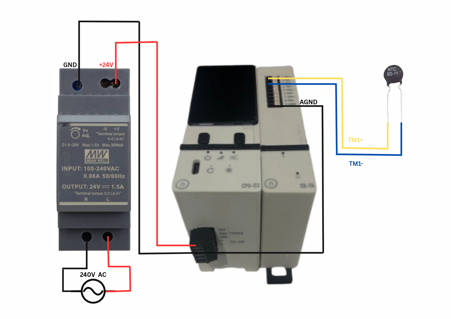
- Connect the thermistor’s two leads to TM1+ and TM1−, and tie AGND to the analog ground reference as in Figure 2.
- Connect the 24 V DC supply to the X-CPU power terminals, then power on.
Sensor wiring practice #
The thermistor is a passive, two-wire sensor. It needs no separate power and has no polarity, so either lead can go on TM1+. Use shielded twisted-pair cable, ground the shield at one end only, keep the leads short, and route them away from motor, VFD, AC and relay wiring. Before wiring, check the probe with a multi meter: it should read about 10kΩ at 25 °C. TM2 to TM4 wire the same way and are read with readADC_SingleEnded(1) to (3). The X-T4 defaults to 0x48, which differs from the X-AI4 and X-AV4 default of 0x49, so they do not clash. Two X-T4 modules on one bus need different DIP settings.
How an NTC Thermistor Is Read #
An NTC thermistor is a resistor whose value falls as it gets hotter, and not in a straight line. The X-T4 puts the thermistor in a voltage divider with a 10kΩ bias resistor on a 3.3 V supply. The ADS1115, set to GAIN_ONE (±4.096 V), measures the voltage across the bias resistor at 125 µV per count. The sketch then recovers the thermistor resistance:
R_ntc = R_bias × (3.3 V ÷ V_adc − 1)
- Open and short detection. An open sensor leaves the divider at about 0 V and a shorted sensor pushes it to about 3.3 V. The sketch accepts only 1 mV to 3.299 V, so both faults are caught.
- Falling sensitivity. As the thermistor resistance drops far below 10kΩ, the divider voltage changes less per degree. This limits resolution at high temperature (see Section 5).
Convert Resistance to Temperature #
The Beta equation converts the thermistor resistance to temperature. T is in kelvin, T0 = 298.15 K (25 °C), R0 = 10kΩ and B = 3892 K:
1/T = 1/T0 + ln(R ÷ R0) ÷ B T(°C) = T − 273.1
For example, R_ntc = 3.64kΩ gives 1/T = 1/298.15 + ln(0.364) ÷ 3892, which is 323.2 K or 50.0 °C. The sketch averages four ADS1115 conversions at 860 samples per second every 100ms, then smooth the result with a 0.15 factor. It declares a fault only after five bad reads in a row (0.5 s), so one noisy sample never flashes an error. Use the values below to check the conversion during commissioning.
| Temperature | R_ntc | Divider voltage | Expected count | Resolution per ADC count |
|---|---|---|---|---|
| 0 °C | 33.0kΩ | 0.767 V | 6136 | < 0.01 |
| 25 °C | 10.0kΩ | 1.650 V | 13200 | < 0.01 |
| 50 °C | 3.64kΩ | 2.419 V | 19351 | < 0.01 |
| 100 °C | 725 Ω | 3.077 V | 24615 | 0.02 °C |
| 150 °C | 211 Ω | 3.232 V | 25853 | 0.09 °C |
| 300 °C | 19 Ω | 3.294 V | 26350 | 1.7 °C |
Ideal Beta model, B = 3892 K, 10kΩ bias, 3.3 V. Real probes vary with their tolerance.
Compensation offset. The sketch adds (coldJunctionTemp − 25) × 0.02 °C to the result. coldJunctionTemp defaults to 25 °C, so the offset is zero. “Cold junction” is a thermocouple term: a thermistor has no cold junction. Here it simply trims the reading for the temperature of the electronics and terminal area. Feed it a measured enclosure temperature if you want the trim, and calibrate the 0.02 factor against a reference thermometer.
Know your limits. The X-T4 datasheet rates the sensor input for probes of at least −40 to +125 °C, and the table shows resolution dropping from 0.09 °C per count at 150 °C to about 1.7 °C per count at 300 °C. The 300 °C limit in this tutorial is an example. Confirm your probe’s rating and the accuracy you need. For higher temperatures use the thermocouple or RTD expansion module from the NORVI X range.
Alarms, Rate of Rise and Fault Detection #
Temperature zones #
The monitor sorts every reading into Normal, Warning or Over-temp. The warning zone starts at 85 % of the limit. Once the over-temperature alarm trips, it stays on until the temperature falls 5 °C below the limit, which stops the screen from chattering near 300 °C.
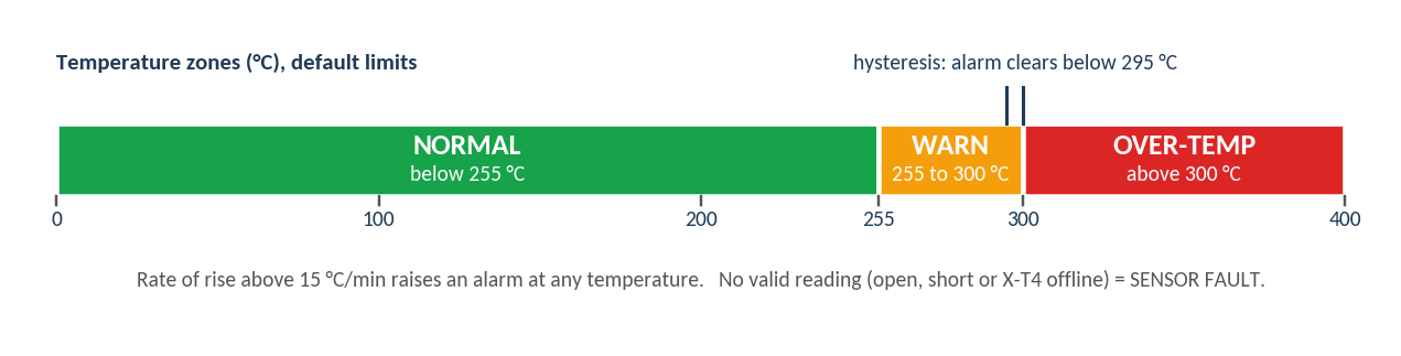
| State | Condition | Display | Header LED |
|---|---|---|---|
| Normal | Below 255 °C | Green value, SYSTEM NORMAL | Green |
| Warning | 255 to 300 °C | Amber value, TEMP WARNING | Amber |
| Over-temp | Above 300 °C (clears below 295 °C) | Red value, ! OVER TEMP ! | Red, blinking |
| Rate alarm | Rise above 15 °C/min | Red rate, ! RISE TOO FAST ! | Red, blinking |
| Sensor fault | Open, short or X-T4 offline | SENSOR OPEN or X-T4 OFFLINE | Red, blinking |
Rate of rise #
Every 3 seconds the sketch stores one temperature sample, 100 in total (5 minutes of trend). The rate of rise is the current temperature minus the sample from 60 seconds earlier, in °C/min. The display shows -- until the first minute of data exists. The value turns amber above 70 % of the 15 °C/min limit and red above it, and the alarm works at any temperature. For example, a zone that climbs from 82.0 °C to 98.5 °C in one minute reads +16.5 °C/min and raises the alarm long before the over-temperature limit.
Sensor fault detection #
| Condition | Meaning | Firmware action |
|---|---|---|
| About 0 V at the ADC | Open thermistor or broken wire | After 5 bad reads: SENSOR OPEN, value hidden, red banner |
| About 3.3 V at the ADC | Shorted leads or terminals | Same as open: SENSOR OPEN |
| No ADS1115 answer | X-T4 not seated, DIP address mismatch or I²C fault | X-T4 OFFLINE banner, retries every 2 s |
| 1 mV to 3.299 V | Valid measurement | Convert to °C, then evaluate zones and rate |
Reading the screen #
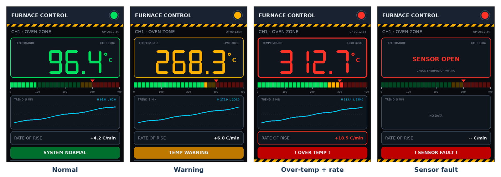
- Header LED shows the state: green, amber, or blinking red.
- 7-segment value shows the temperature in the state color.
- Bar gauge runs from 0 to 400 °C with a red marker at the limit.
- Trend shows the last 5 minutes with the high and low values.
- Rate of rise panel and the status banner with a hazard stripe in alarm.
Arduino Code for the ESP32 Thermistor Monitor #
Set up the IDE #
- Select ESP32S3 Dev Module, then set USB CDC On Boot to Enabled, Flash Size to 16MB (128Mb) and PSRAM to QSPI PSRAM.
- Install Adafruit ADS1X15 (with its BusIO dependency) and LovyanGFX from the Library Manager. Wire, SPI and math come with the ESP32 core.
How the sketch works #
- Non-blocking timing.
millis()schedules sensing every 100ms, trend samples every 3 s, redraws every 200ms and Serial output every second, so nothing stalls the loop. - Off-screen sprite. Each frame is drawn into a 240 × 320 buffer and pushed to the TFT in one go, which removes flicker. If RAM is short it falls back to 8-bit color and prints a message.
- Trend buffer. A 100-point array holds the last 5 minutes and feeds both the graph and the 60-second rate of rise.
What the main parts of the code do #
The complete sketch is available on Application program for Furnace/Oven Temperature Monitor. In order, its main parts do the following:
- Settings. Holds the sensor constant, the alarm limits, the hysteresis, the rate-of-rise limit and the timing. These are the values you change to suit your probe and process.
- Reading the sensor. Takes four quick readings from channel 1 of the X-T4 and averages them to reduce noise.
- Converting to temperature. Turns the voltage into the thermistor’s resistance, applies the Beta equation to get °C, and adds the small compensation offset. A voltage outside the valid window is treated as an open or shorted sensor.
- Smoothing and fault check. Smooths the temperature so the display does not jump, and declares a sensor fault only after five bad readings in a row.
- X-T4 monitoring. Sets the ADC range and speed at start-up. If the X-T4 stops answering, the screen shows X-T4 OFFLINE and the sketch keeps retrying every 2 seconds.
- Trend and rate of rise. Every 3 seconds it saves one temperature sample into a 5-minute history. The rate of rise is how much the temperature changed over the last 60 seconds, in °C/min.
- Alarm decision. Sorts the reading into Normal, Warning or Over-temp. Over-temp stays on until the temperature falls 5 °C below the limit. A fast rate of rise or an invalid reading also raises an alarm.
- Drawing the screen. Draws the header, large value, bar gauge, trend graph, rate panel and status banner off-screen, then sends the finished picture to the display in one step, so nothing flickers.
- Start-up. Holds the Ethernet and SD card chip-selects high so they stay off the shared SPI bus, scans the I²C bus, starts the display, and creates the drawing buffer (falling back to lower color depth if memory is short).
- Main loop. Never waits. Sensing runs every 100ms, the trend every 3 seconds, the display every 200ms and the Serial output once per second.
Commissioning and Test #
Commissioning checklist #
- Power supply. Verify that the 24 V DC supply is stable and correctly wired to the NORVI X-CPU-ESPS3-X1 before you energize the system.
- I²C addresses. Confirm the DIP switches set 0x48 and the Serial Monitor shows no “ADS1115 not found” message. For a full check, run the I²C scan below.
- Resistor substitution. Replace the probe with a precision 10kΩ resistor: the display should read about 25 °C. A 3.6kΩ resistor should read about 50 °C.
- Ice-water check. Put the probe in melting ice water. It should settle near 0 °C within the probe’s tolerance.
- Thresholds. Temporarily set
MAX_SAFE_TEMPto 40 °C, warm the probe in your hand or in warm water, and confirm the Warning and Over-temp states, then restore the limit. - Rate of rise. Move the probe from room air into warm water (about 60 °C). After the first minute the rate should read well above 15 °C/min and trigger the rate alarm.
- Fault response. Disconnect one thermistor lead. SENSOR OPEN should appear within about a second.
To scan the I²C bus, call this function from setup() after Wire.begin(). The scan lists 0x48 (X-T4), 0x41 (PCA9536), 0x15 (touch controller), 0x68 (RTC) and 0x75 (I/O expander). The sketch already calls it at start-up.
void i2cScan() {
  for (byte a = 1; a < 127; a++) {
    Wire.beginTransmission(a);
    if (Wire.endTransmission() == 0) Serial.printf("  found 0x%02X\n", a);
  }
}
Expected output #
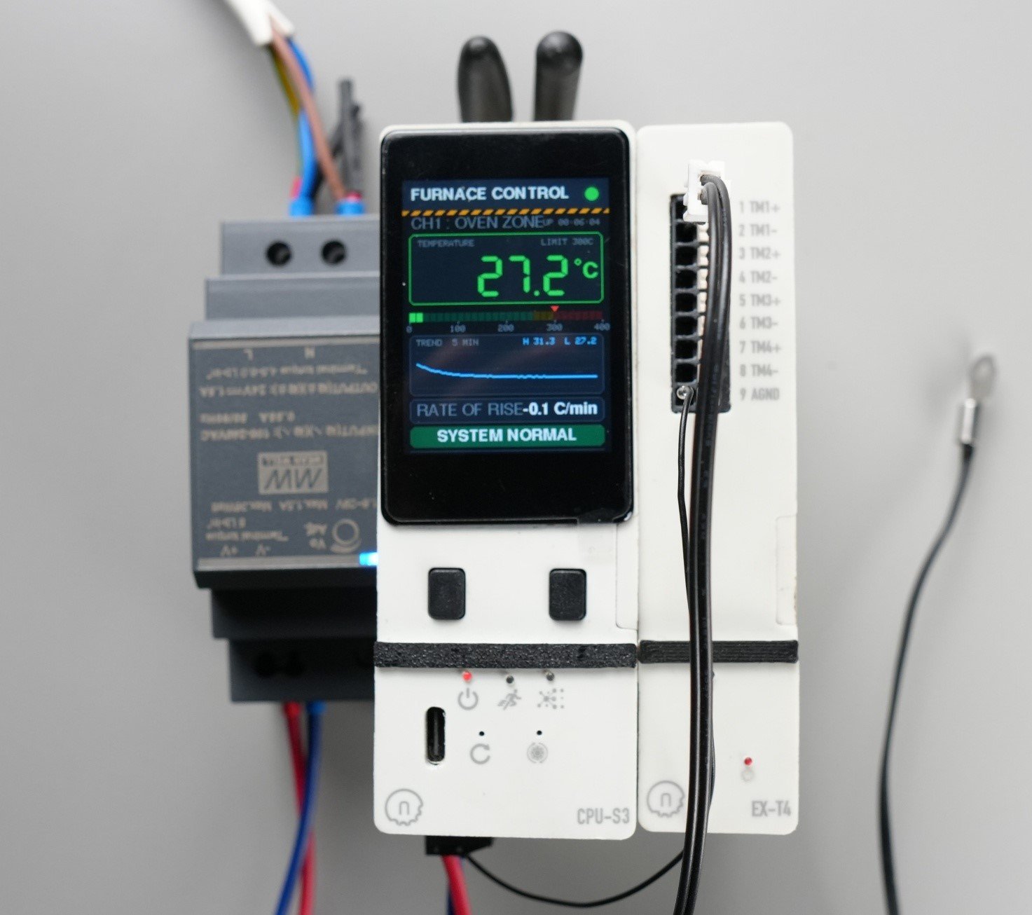
The Serial Monitor prints one line per second, for example Furnace Z1: 25.43 C | RoR: 0.2 C/min. The rate prints as nan during the first minute while the display shows --. Figure 4 shows the four display states.
Troubleshooting #
| Symptom | Likely cause | Remedy |
|---|---|---|
| Display blank or white | Wrong SPI pins, display bus not initialized, or Tools settings | Confirm CS 45, DC 46 and RST 47 in the LGFX class. Set USB CDC On Boot, Flash Size and PSRAM as in 7.1. |
| X-T4 OFFLINE | Module not seated, or DIP address does not match ADS_ADDR | Power off and reseat the X-T4. Set DIP 4 ON for 0x48 and run the I²C scan. |
| SENSOR OPEN | Broken lead, loose terminal or shorted leads | Check the leads on TM1+ and TM1−. With power off, the probe should measure about 10 kΩ at 25 °C. |
| Negative or erratic temperature | Wrong sensor type, damaged probe or noise pickup | Confirm a 10 kΩ NTC. Use shielded twisted pair and keep it away from motor and relay wiring. |
| Temperature offset from actual | B value or divider constants do not match the probe | Set B_COEFFICIENT to your probe (3892 or 3950 K), compare with a reference thermometer, and trim the offset. |
| Rate alarm triggers unexpectedly | Draught, a poorly seated probe or a nearby heat source | The rate is a 60-second difference, so fix the probe mounting first, then raise RATE_OF_RISE_LIMIT if needed. |
| Alarm flickers near 300 °C | Temperature hovers at the limit | Increase TEMP_HYSTERESIS. |
| Wrong or coarse at high temperature | Beyond the probe rating, or limited divider resolution | See the limits note in Section 5. Use a high-temperature probe or a thermocouple or RTD module. |
Safety. Disconnect all power before wiring, and let a qualified electrician install the system. This monitor provides indication only. Never use it as a safety function.
FAQ #
It can, but the ESP32’s own ADC is noisy and non-linear. The X-T4 provides a stable 3.3 V divider and a 16-bit ADS1115, so your sketch reads clean values over I²C.
Any 10kΩ (R25) NTC works. Set B_COEFFICIENT to your probe’s datasheet value. The X-T4 datasheet quotes about 3950 K, and this tutorial uses 3892 K for the Littelfuse 103JG1K. A wrong B value shows up as an error that grows away from 25 °C.
Cold-junction compensation is a thermocouple term. The sketch uses the same idea as an offset trim for the electronics temperature, which is explained in Section 5.
Yes. The X-T4 has four channels. Read AIN1 to AIN4 with readADC_SingleEnded (1) to (4), and keep a separate trend buffer, rate and alarm state for each zone.
Only with a probe rated for it, and with reduced resolution (Section 5). For furnace work above the probe rating, use the thermocouple or RTD expansion module.
Conclusion #
You now have a working ESP32 thermistor temperature monitor that reads a 10kΩ NTC on the X-T4, converts it to °C with a compensation offset, tracks the rate of rise, and raises warning, over-temperature, rate and sensor-fault alarms on the X-CPU display. To go further, monitor all four channels, publish the readings over MQTT, log them to the SD card, or switch a relay output on alarm.
Resources
NORVI X-CPU-ESPS3-X1 user guide | NORVI X-CPU-ESPS3-X1 datasheet