
Overview #
The NORVI X is a modular, DIN-rail industrial IoT controller built around the ESP32-S3 processor. Its CPU module includes a Wiznet W5500 Ethernet PHY alongside RS-485, Wi-Fi and Bluetooth, so the same controller can speak Modbus over a wired network as well as over a serial bus.
Modbus TCP is the Ethernet-based version of the Modbus protocol: it carries the same read/write requests as Modbus RTU, but wraps them in a TCP/IP packet instead of a serial frame, and it uses TCP port 502 by default.
In a Modbus TCP conversation, the device that initiates requests is the master (also called the client); the device that answers them is the slave (server). This guide covers the master role: configuring a NORVI X to poll and write to other Modbus TCP slave devices – such as energy meters, VFDs, remote I/O modules or other PLCs – over Ethernet.
Key Features #
- Native Ethernet (RJ45) port via the on-board W5500 controller – no external gateway hardware needed.
- Acts as a Modbus TCP master or slave; the two roles can also run side by side on the same device.
- Polls multiple Modbus TCP slaves – energy meters, VFDs, remote I/O, other PLCs – and aggregates the data locally or forwards it over MQTT/HTTP.
- Static IP or DHCP addressing, configurable through the NORVI X web interface or in firmware.
- Fully programmable in the Arduino IDE, ESP-IDF or MicroPython.
- Can bridge a Modbus TCP network to Modbus RTU devices on its RS-485 port, or to OPC-UA / MQTT for SCADA and cloud integration.
Safety Information #
For Modbus TCP communication, connect the NORVI X controller to the Ethernet network using a standard network (Ethernet) cable. The controller communicates with the Modbus TCP Master or Slave through the Ethernet network.
Requirements #
- A NORVI X CPU module (e.g. CPU-ESPS3-X1/X2/X3) with its Ethernet port.
- One or more Modbus TCP slave devices, or a Modbus TCP simulator (e.g. Diagslave, ModbusPal, or Modbus Poll/Slave running on a PC) for bench testing.
- A network switch/router, or a direct Ethernet link between the NORVI X and the slave device for testing.
- Arduino IDE with ESP32 board support installed.
- USB cable for programming the NORVI X CPU module.
Network & Hardware Setup #
Physical Connection #
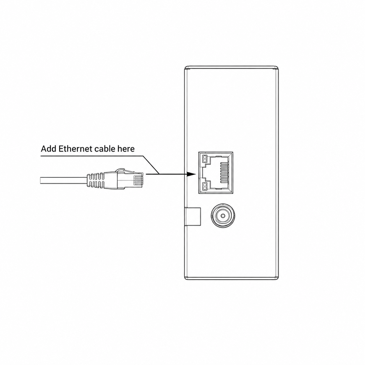
- Connect the NORVI X’s RJ45 Ethernet port to your network switch, router, or directly to the slave device with an Ethernet cable.
- Power the NORVI X CPU module per its datasheet (typically 24 V DC).
- Note the IP address of each Modbus TCP slave you intend to poll – these will be entered in firmware or in the web configuration.
Addressing #
Assign the NORVI X a static IP address for predictable communication, or use DHCP for simpler installations where the network handles addressing. Static addressing is generally preferred for master devices, since the slave list is addressed by IP and an unexpected address change will break polling.
Modbus TCP uses TCP port 502 by default. Confirm that this port is open between the NORVI X and each slave device (no firewall or VLAN blocking it).
Software Setup (Arduino IDE) #
Board Configuration #
- Install ESP32 board support in the Arduino IDE
- Select the NORVI X CPU module’s board profile under Tools → Board.
- Connect the CPU module via USB and select the correct COM/serial port under Tools → Port.
Required Libraries #
Install these libraries via Sketch → Include Library → Manage Libraries:
| Library | Purpose |
|---|---|
| Ethernet (v2) | Low-level driver for the W5500 Ethernet chip |
Modbus TCP Master – Code Example #
This example demonstrates how a NORVI X Controller operates as a Modbus TCP Master using the W5500 Ethernet interface. The master connects to a Modbus TCP slave, reads Holding Registers using FC03, and writes a Single Register using FC06.
Ethernet Configuration #
The X-CPU communicates with the W5500 Ethernet chip over SPI. At startup the code releases the Ethernet port from reset and starts SPI:
digitalWrite(38, HIGH);              // release Ethernet port from reset
SPI.begin(SCLK, MISO, MOSI);
Ethernet.init(ETH_CS);
The board then requests an IP address by DHCP. If DHCP fails, it uses the static IP 192.168.1.50:
if (Ethernet.begin(mac) == 0) {
Ethernet.begin(mac, localIP); // static IP fallback
}
The board then finds the slave by trying to connect to port 502 on every address in its own subnet (.1 to .254). The first device that accepts the connection is used as the slave:
if (client.connect(ip, slavePort)) {
  slaveIP = ip;                      // slave found
}
The master and the slave must be on the same subnet.
Read Holding Registers – FC03 #
The master asks the slave for 4 registers, starting at address 0:
readHoldingRegs(0, 4, regs); // start address 0, read 4 registersEach register arrives as 2 bytes (high byte first), and the code joins them into one value:
out[i] = (resp[9 + i * 2] << 8) | resp[10 + i * 2];The values are printed on the Serial Monitor:
Holding regs 0-3: 100 200 300 400Write Single Register – FC06 #
The master writes a value to register 10. The value is a counter that increases after every write:
writeSingleReg(10, counter++); // write to register 10The slave replies with a copy of the request to confirm the write. The code treats the write as successful when the reply is 12 bytes:
return n >= 12;Serial Monitor output:
Wrote reg 10 = 0
Wrote reg 10 = 1
Testing the Code #
- Configure the Modbus TCP Slave
Set the slave to use TCP port 502 and Unit ID 1. Configure holding registers 0-3 for reading and register 10 for writing. - Set Test Values
Enter known values in holding registers 0-3, for example:
Register 0: 100
Register 1: 200
Register 2: 300
Register 3: 400 - Connect the Devices
Connect the NORVI X controller and the Modbus TCP slave to the same Ethernet network. - Upload and Run the Code
Upload the Modbus TCP Master code to the NORVI X controller. Open the Serial Monitor and set the baud rate to 115200. - Verify the Results
The controller automatically scans the local subnet and connects to the Modbus TCP slave. It then reads registers 0-3 using Function Code 03 (FC03) and writes an incrementing value to register 10 using Function Code 06 (FC06).
A successful test should produce output similar to:
Slave found at: 192.168.1.100
Holding regs 0-3: 100 200 300 400
Wrote reg 10 = 0
Holding regs 0-3: 100 200 300 400
Wrote reg 10 = 1
The complete source code is available on GitHub.
GitHub: View Modbus TCP Master Example
Modbus TCP Slave – Code Example #
This example demonstrates how a NORVI X Controller operates as a Modbus TCP Slave using the W5500 Ethernet interface. The Slave listens on port 502 and provides a register table that can be accessed by a Modbus TCP Master.
Ethernet Configuration #
The Ethernet setup is the same as in the master code. The board releases the Ethernet port from reset, starts SPI, and gets an IP address by DHCP, with the static IP 192.168.1.50 as a fallback:
SPI.begin(SCLK, MISO, MOSI);
Ethernet.init(ETH_CS);
if (Ethernet.begin(mac) == 0) {
Ethernet.begin(mac, localIP);
}Modbus TCP Slave Configuration #
The slave listens on TCP port 502, uses Unit ID 1, and provides 100 Modbus registers:
ModbusServer server(502);const uint8_t unitId = 1;
const uint16_t NUM_REGS = 100;
uint16_t regs[NUM_REGS];Register Values #
The example initializes Registers 1 and 2 with test values:
regs[1] = 1000;
regs[2] = 2000;
Register 0 is updated every second with the controller uptime:
if (millis() - lastUpdate >= 1000) {
    lastUpdate = millis();
    regs[0] = millis() / 1000;
}
Supported Modbus Functions #
The slave processes the following function codes:
if (fc == 0x03 || fc == 0x04) {
    // Read registers

} else if (fc == 0x06) {
    // Write single register

} else if (fc == 0x10) {
    // Write multiple registers
}| Function Code | Operation |
|---|---|
| FC03 | Read Holding Registers |
| FCO4 | Read Input Registers |
| FC06 | Write Single Register |
| FC16 (0x10) | Write Multiple Registers |
Request Handling and Polling #
The slave waits for requests from the Modbus TCP master:
EthernetClient c = server.available();
if (c)
    handleRequest(c);
The master performs the polling by sending read or write requests. The slave processes each request and returns the corresponding response.
Testing the Code #
- Connect the NORVI X controller to the network using an Ethernet cable.
- Upload the Modbus TCP Slave code and open the Serial Monitor at 115200 baud.
- Note the IP address displayed in the Serial Monitor:
Modbus TCP slave listening at 192.168.1.50:502 (Unit ID 1) - Connect a Modbus TCP master to the slave using the displayed IP address, TCP port 502, and Unit ID 1.
- Read holding registers 0-3 from the master. The registers contain:
- Register 0: Controller uptime in seconds; this value increases continuously.
- Register 1: Initial value of 1000.
- Register 2: Initial value of 2000.
- Register 3: Default value until it is written by a Modbus master.
- Write a value to register 10 from the Modbus TCP master. The slave displays the received value in the Serial Monitor.
The complete source code is available on GitHub.
GitHub: View Modbus TCP Slave Example
Troubleshooting #
| Symptom | Likely Cause | Action |
|---|---|---|
| Master cannot connect to slave / connection times out | Wrong slave IP address, or TCP port 502 blocked by firewall/VLAN | Verify the slave’s IP with a ping, and confirm port 502 is open between the two devices |
| No response to read/write requests | Wrong Unit ID, or slave is not listening on port 502 | Check the unitId matches the slave’s configured address; confirm the slave is powered and initialized |
| Register values look like garbage / out of range | Byte order mismatch, or reading the wrong register count for a multi-register (e.g. 32-bit float) value | Confirm the slave’s register map and byte/word order (big- vs little-endian) in its documentation |
| IP address changes unexpectedly, polling breaks | Device was left on DHCP | Assign a static IP to master and/or slave devices, per Section 5.2 |
| Values write successfully but don’t take effect on the slave device | Wrong register address, or the register is read-only on that device | Cross-check the target register address against the slave device’s Modbus map |