
A step-by-step tutorial for planning valid NORVI X CPU + expansion module combinations.
Every NORVI X expansion module talks to the CPU over a shared I2C bus, while a few use a dedicated interface instead. Because devices on the same bus must have unique I2C addresses, each type of expansion chip has a limited number of addresses available. This limits how many modules of that type can be stacked on one CPU.
This tutorial explains how to determine which NORVI X expansion modules can be combined and how many of each can be used in a system.
Two ways modules connect to the CPU #
I2C bus (most modules): X-DI8, X-DA8, X-R4, X-R8, X-Q8, X-DI16, X-Q16, X-AV4, X-AI4, X-AQ4, X-T4, X-TC4, X-MX4 and X-RTD4 share the same I2C bus. Each module is identified by a unique address configured using its DIP switch.
Direct GPIO (a few modules): X-DI4, X-Q4 and X-UARTIO skip I2C communication and connect directly to dedicated GPIO pins on the CPU. Their limitations depend on the physical GPIO pins available rather than I2C address counts.
Understand what’s actually behind each module #
Most of the NORVI X expansion line-up communicates with the CPU over I2C. Several different chips are used across these modules, and modules that share the same chip also share the same limited pool of I2C addresses.
X-DI4, X-Q4 and X-UARTIO are exceptions because they use dedicated GPIO pins instead.
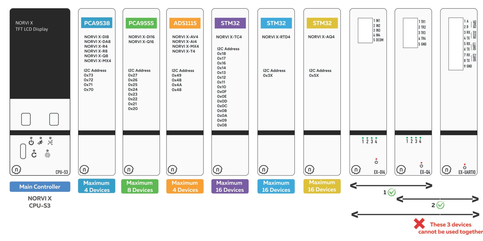
| Chip Type | Modules Using It | Maximum on One CPU |
|---|---|---|
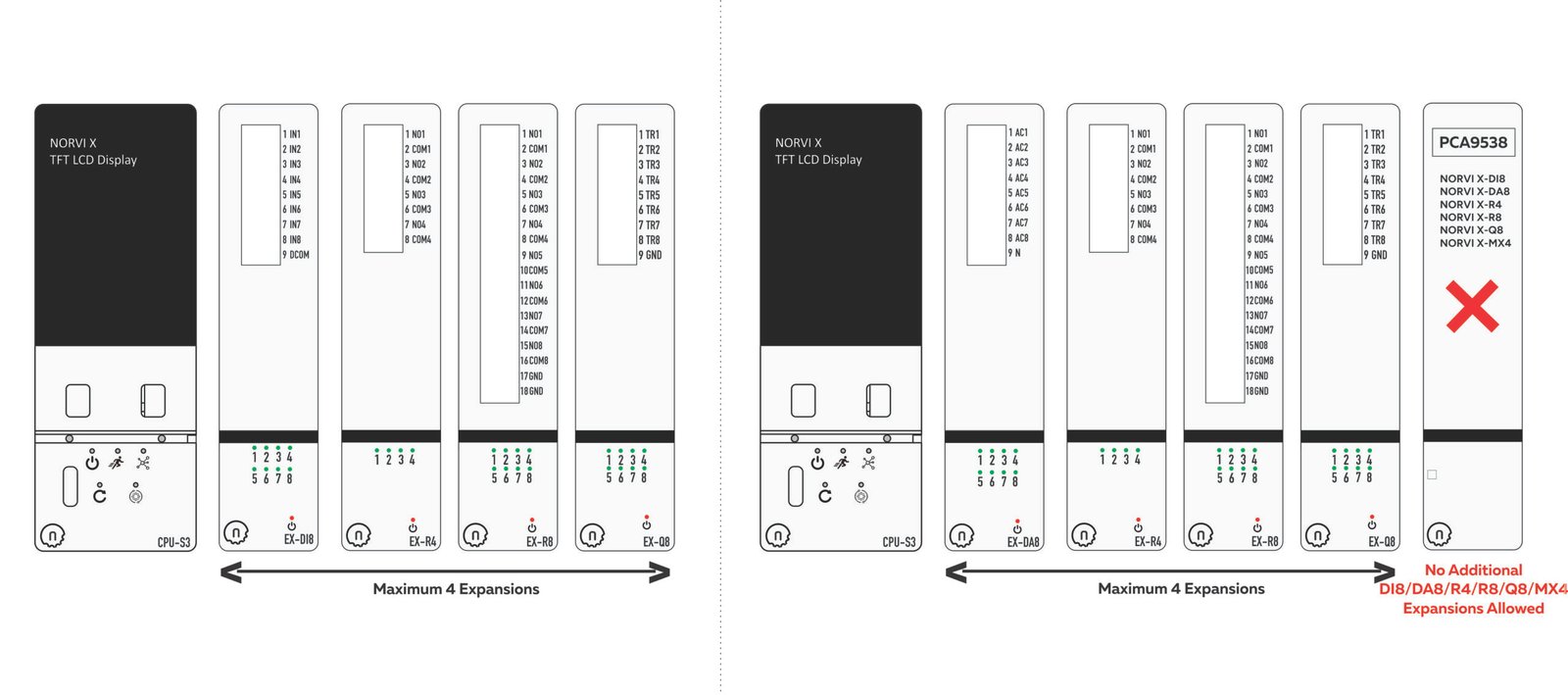
| PCA9538 8-bit GPIO expander | X-DI8, X-DA8, X-R4, X-R8, X-Q8, X-MX4 | 4 |
| PCA9555 16-bit GPIO expander | X-DI16, X-Q16 | 8 |
| ADS1115 16-bit ADC | X-AV4, X-AI4, X-MX4, X-T4 | 4 |
| STM32 Microcontroller | X-AQ4, X-RTD4, X-TC4 | 16 |
All devices on the same I2C bus must have a unique address. A chip with only four configurable addresses can therefore appear only four times on one CPU, regardless of which modules using that chip are selected.
Check for GPIO pin conflicts #
Three modules, X-DI4, X-Q4 and X-UARTIO, use dedicated GPIO pins directly on the CPU rather than relying entirely on I2C communication.
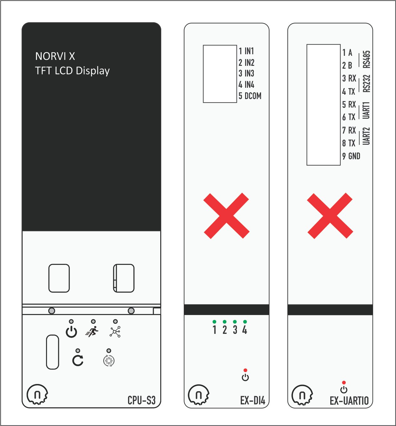
X-DI4 and X-UARTIO use the same GPIO pins, creating a direct pin conflict. Therefore, they cannot be installed together.
| Combination | Result |
|---|---|
| X-UARTIO + X-DI4 + X-Q4 | Cannot use all three together |
| X-UARTIO + X-DI4 | Cannot use due to pin conflict |
| X-DI4 + X-Q4 | Can use |
| X-UARTIO + X-Q4 | Can use |
| Expansion Module | GPIO Pins Used |
|---|---|
| NORVI X-DI4 | GPIO5, GPIO6, GPIO7, GPIO10 |
| NORVI X-UARTIO | GPIO5, GPIO6, GPIO7, GPIO10 |
| NORVI X-Q4 | GPIO35, GPIO41, GPIO13, GPIO14 |
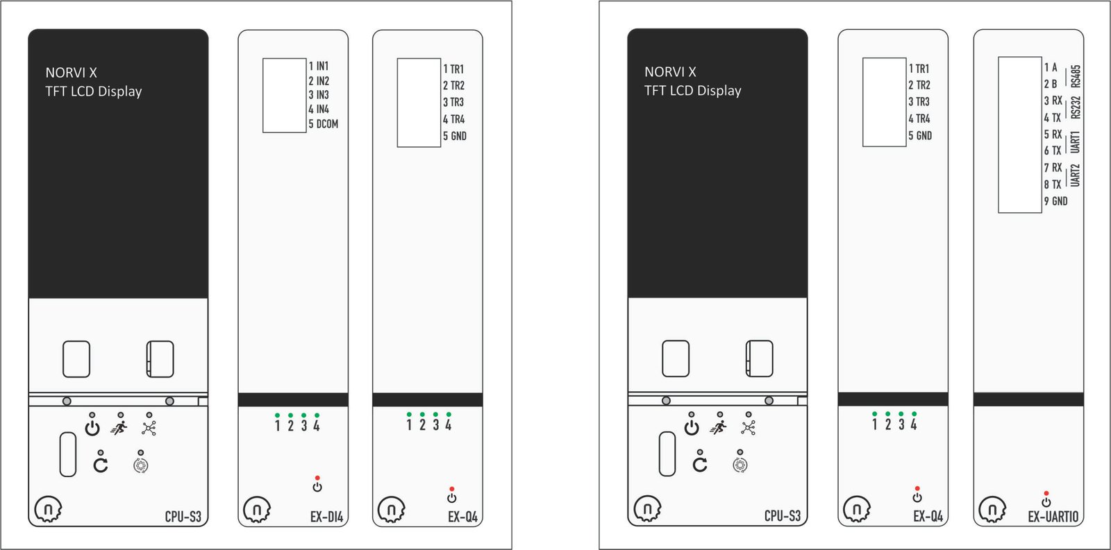
Rule of thumb: Use either X-DI4 + X-Q4 or X-Q4 + X-UARTIO on a CPU. Do not use all three together, and do not combine X-DI4 with X-UARTIO.
Know the address limit for each chip #
Each I2C chip family provides a fixed number of selectable addresses configured through the module’s DIP switches. This determines the maximum number of modules from that chip family that can share one bus.
PCA9538 – up to 4 modules #
The PCA9538 is used by X-DI8, X-DA8, X-R4, X-R8, X-MX4 and X-Q8. Only four addresses are available, so the total number of PCA9538-based expansion modules connected to a single CPU cannot exceed four.
| DIP 1 | DIP 2 | DIP 3 | DIP 4 | Address |
|---|---|---|---|---|
| OFF | OFF | 0x73 | ||
| ON | OFF | 0x72 | ||
| OFF | ON | 0x71 | ||
| ON | ON | 0x70 |
PCA9555 – up to 8 modules #
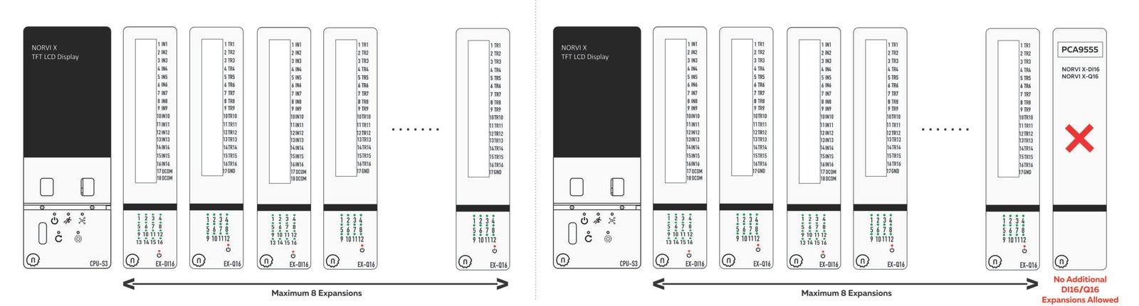
The PCA9555 is used by X-DI16 and X-Q16. It provides eight selectable addresses, allowing up to eight modules from this group to be mixed on a single CPU.
The total number of PCA9555-based expansions connected to one CPU cannot exceed eight.
| DIP 1 | DIP 2 | DIP 3 | DIP 4 | Address |
|---|---|---|---|---|
| OFF | OFF | OFF | 0x27 | |
| ON | OFF | OFF | 0x26 | |
| OFF | ON | OFF | 0x25 | |
| ON | ON | OFF | 0x24 | |
| OFF | OFF | ON | 0x23 | |
| ON | OFF | ON | 0x22 | |
| OFF | ON | ON | 0x21 | |
| ON | ON | ON | 0x20 |
ADS1115 – up to 4 modules #
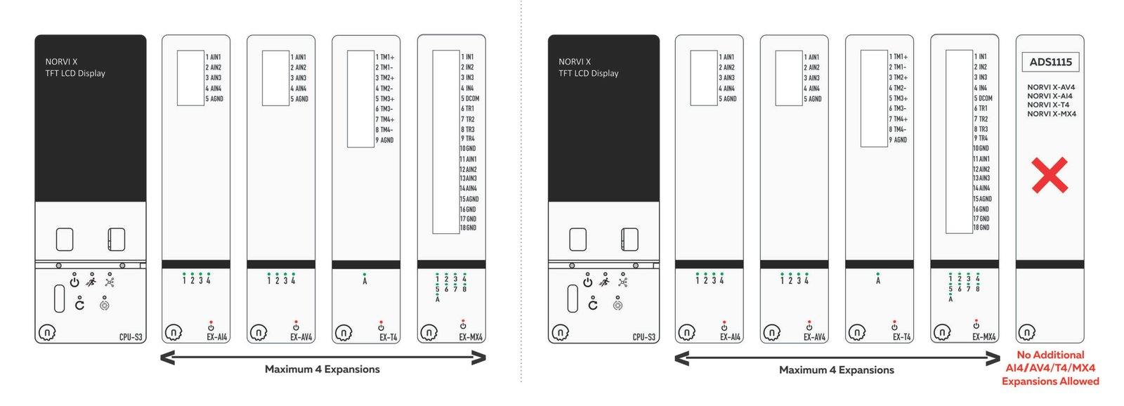
The ADS1115 is used by X-AV4, X-T4, X-MX4 and X-AI4 for analog input. Four addresses are available, so up to four ADS1115-based modules can be connected in any combination.
The total number of ADS1115-based expansion modules connected to a single CPU cannot exceed four.
| DIP 1 | DIP 2 | DIP 3 | DIP 4 | Address |
|---|---|---|---|---|
| ON | OFF | OFF | OFF | 0x49 |
| OFF | ON | OFF | OFF | 0x4B |
| OFF | OFF | ON | OFF | 0x4A |
| OFF | OFF | OFF | ON | 0x48 |
STM32-based modules – up to 16 modules each #
X-AQ4, X-TC4 and X-RTD4 each use an STM32 microcontroller as an I2C slave, with 16 selectable addresses of their own.
NORVI X-AQ4 #
The NORVI X-AQ4 expansion module uses an STM32 microcontroller for communication and supports 16 configurable I2C addresses in the 0x5X address range, allowing up to 16 modules on a single I2C bus.
| DIP 1 | DIP 2 | DIP 3 | DIP 4 | Address |
|---|---|---|---|---|
| OFF | OFF | OFF | OFF | 0x5F |
| ON | OFF | OFF | OFF | 0x57 |
| OFF | ON | OFF | OFF | 0x5B |
| ON | ON | OFF | OFF | 0x53 |
| OFF | OFF | ON | OFF | 0x5D |
| ON | OFF | ON | OFF | 0x55 |
| OFF | ON | ON | OFF | 0x59 |
| ON | ON | ON | OFF | 0x51 |
| OFF | OFF | OFF | ON | 0x5E |
| ON | OFF | OFF | ON | 0x56 |
| OFF | ON | OFF | ON | 0x5A |
| ON | ON | OFF | ON | 0x52 |
| OFF | OFF | ON | ON | 0x5C |
| ON | OFF | ON | ON | 0x54 |
| OFF | ON | ON | ON | 0x58 |
| ON | ON | ON | ON | 0x50 |
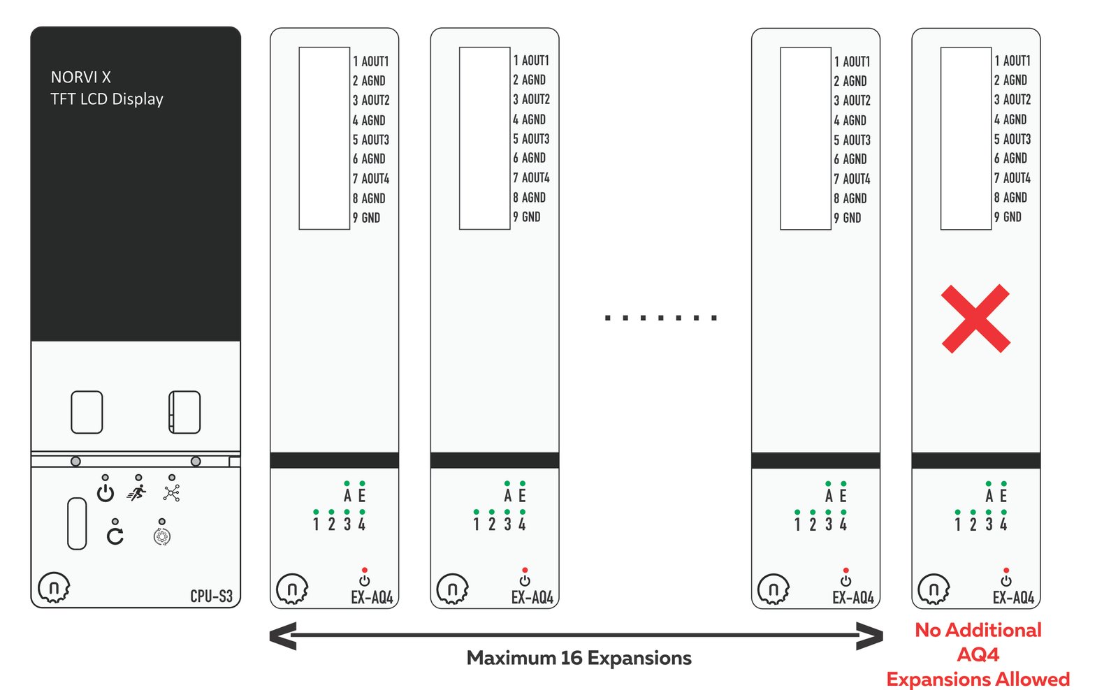
The STM32-based NORVI X-AQ4 provides 16 unique I2C addresses in the 0x5X range. Each address can be used only once on the same I2C bus. Therefore, the total number of X-AQ4 expansion modules connected to a single CPU cannot exceed 16.
NORVI X-RTD4 #
The NORVI X-RTD4 expansion module uses an STM32 microcontroller and supports 16 configurable I2C addresses in the 0x3X address range. This allows up to 16 modules to operate on the same I2C bus without address conflicts.
| DIP 1 | DIP 2 | DIP 3 | DIP 4 | Address |
|---|---|---|---|---|
| OFF | OFF | OFF | OFF | 0x3F |
| ON | OFF | OFF | OFF | 0x3E |
| OFF | ON | OFF | OFF | 0x3D |
| ON | ON | OFF | OFF | 0x3C |
| OFF | OFF | ON | OFF | 0x3B |
| ON | OFF | ON | OFF | 0x3A |
| OFF | ON | ON | OFF | 0x39 |
| ON | ON | ON | OFF | 0x38 |
| OFF | OFF | OFF | ON | 0x37 |
| ON | OFF | OFF | ON | 0x36 |
| OFF | ON | OFF | ON | 0x35 |
| ON | ON | OFF | ON | 0x34 |
| OFF | OFF | ON | ON | 0x33 |
| ON | OFF | ON | ON | 0x32 |
| OFF | ON | ON | ON | 0x31 |
| ON | ON | ON | ON | 0x30 |
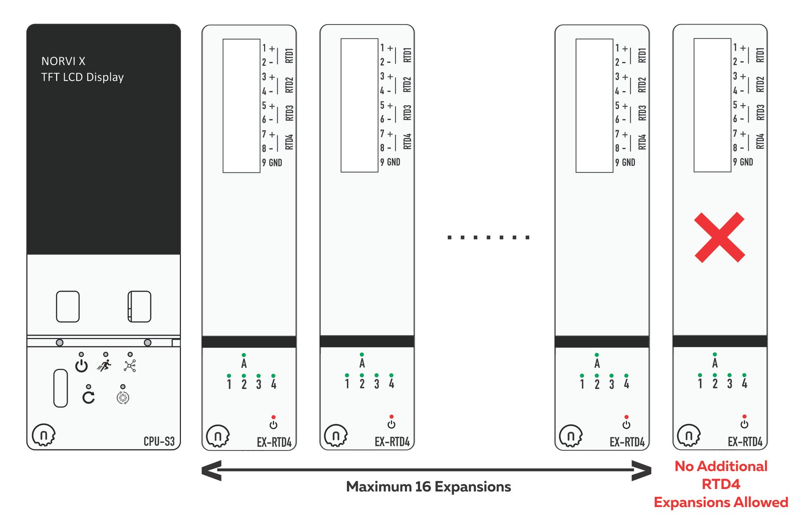
The STM32-based NORVI X-RTD4 provides 16 unique I2C addresses in the 0x3X address range. Each address can be used only once on the same I2C bus. The total number of X-RTD4 expansions connected to a single CPU cannot exceed 16.
NORVI X-TC4 #
The NORVI X-TC4 expansion module also uses an STM32 microcontroller and supports 16 configurable I2C addresses, enabling up to 16 modules to operate on the same I2C bus without address conflicts.
| DIP 1 | DIP 2 | DIP 3 | DIP 4 | Address |
|---|---|---|---|---|
| OFF | OFF | OFF | OFF | 0x18 |
| ON | OFF | OFF | OFF | 0x17 |
| OFF | ON | OFF | OFF | 0x16 |
| ON | ON | OFF | OFF | 0x14 |
| OFF | OFF | ON | OFF | 0x13 |
| ON | OFF | ON | OFF | 0x12 |
| OFF | ON | ON | OFF | 0x11 |
| ON | ON | ON | OFF | 0x10 |
| OFF | OFF | OFF | ON | 0x0F |
| ON | OFF | OFF | ON | 0x0E |
| OFF | ON | OFF | ON | 0x0D |
| ON | ON | OFF | ON | 0x0C |
| OFF | OFF | ON | ON | 0x0B |
| ON | OFF | ON | ON | 0x0A |
| OFF | ON | ON | ON | 0x09 |
| ON | ON | ON | ON | 0x08 |
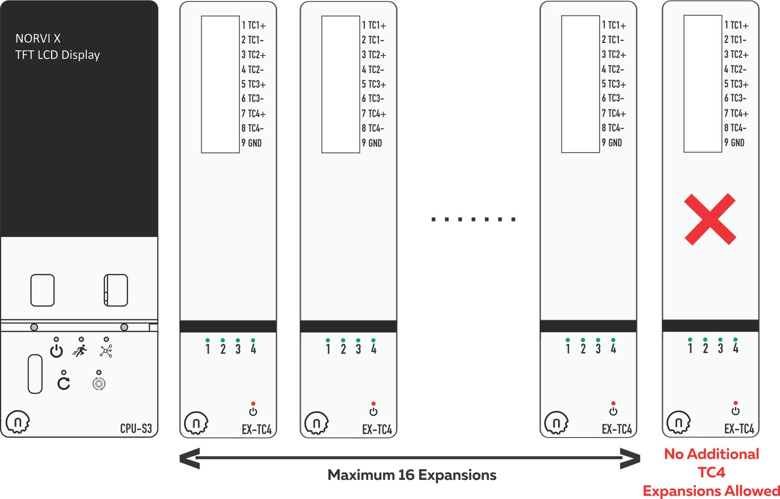
The STM32-based NORVI X-TC4 provides 16 unique I2C addresses. Each address can be used only once on the same I2C bus. Therefore, the total number of X-TC4 expansion modules connected to a single CPU cannot exceed 16.
Quick-reference summary #
Keep this table handy when planning a NORVI X CPU and expansion module configuration.
| Module Group | Members | Maximum Modules Combined |
|---|---|---|
| PCA9538 group | X-DI8, X-DA8, X-R4, X-R8, X-Q8, X-MX4 | 4 |
| PCA9555 group | X-DI16, X-Q16 | 8 |
| ADS1115 group | X-AV4, X-AI4, X-T4, X-MX4 | 4 |
| STM32 | X-AQ4, X-RTD4, X-TC4 | 16 |
| GPIO-pin group | X-DI4, X-Q4, X-UARTIO | See GPIO conflict rule |
Checklist before you order or wire anything #
- Identify the chip family behind every module in your design.
- Confirm that the total count within each chip family does not exceed its address limit.
- If using X-DI4, X-Q4 or X-UARTIO, confirm that only a valid GPIO pairing is used.
- Plan a unique DIP switch setting for every module sharing the same chip family.