
Introduction #
This tutorial explains how to measure temperature using NORVI X expansion modules. It covers two temperature-sensing solutions: the NORVI X-RTD4, which supports PT100 and PT1000 RTD sensors, and the NORVI X-T4, which supports 2-wire NTC thermistors.
Required Hardware #
| Device | Temperature Sensor | Sensor Type | Channels |
|---|---|---|---|
| NORVI X-RTD4 | PT100 / PT1000 | RTD | 4 |
| NORVI X-T4 | NTC Thermistor (10kΩ) | 2-wire NTC | 4 |
Understanding the Sensors #
PT100 / PT1000 #
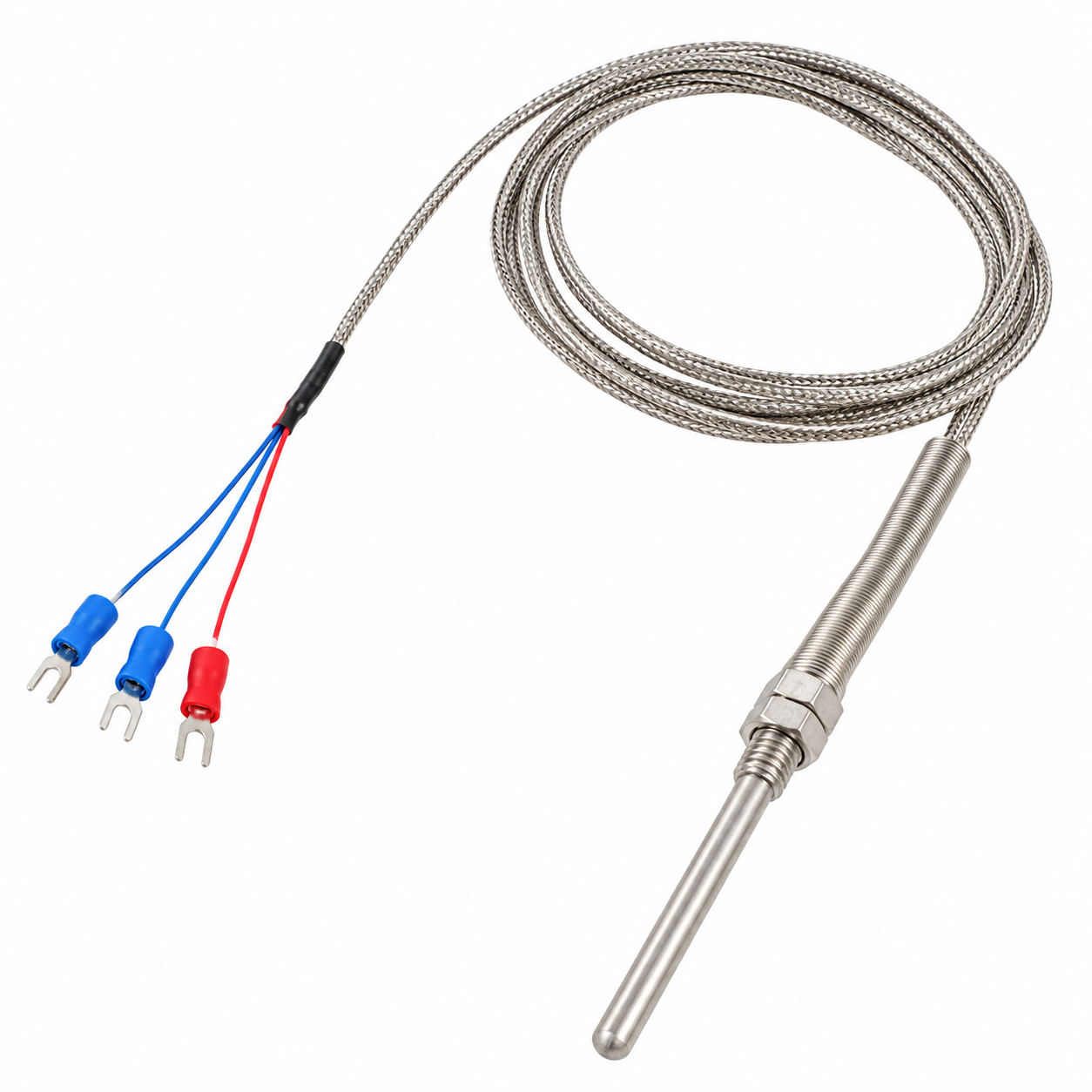
- RTD (Resistance Temperature Detector)
- Resistance changes with temperature
- PT100 = 100 Ω at 0°C
- PT1000 = 1000 Ω at 0°C
- Used with the X-RTD4
NTC Thermistor (10kΩ) #
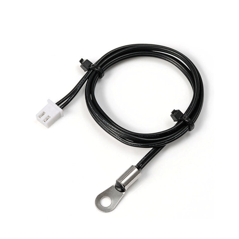
- NTC = Negative Temperature Coefficient
- Resistance decreases as temperature increases
- 2-wire sensor connection
- Used with the X-T4
NORVI X-RTD4 – PT100 / PT1000 #
The NORVI X-RTD4 is a 4-channel RTD temperature input module. It reads 4 sensor inputs and is used in industrial, HVAC, and process monitoring applications.
A. Sensor wiring #
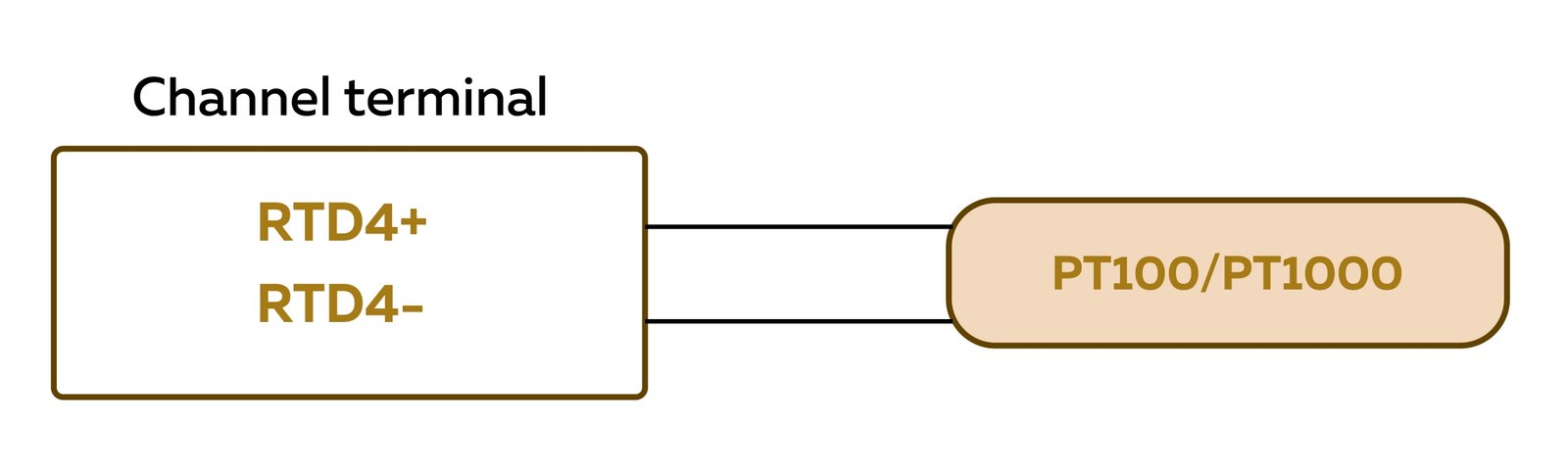
The NORVI X-RTD4 supports PT100 and PT1000 RTD temperature sensors. PT100 has a nominal resistance of 100 Ω at 0°C, while PT1000 has 1000 Ω at 0°C. For a 2-wire connection, connect the two sensor wires to the corresponding RTD input terminals. The X-RTD4 provides four channels (RTD1–RTD4), allowing up to four PT100 or PT1000 sensors to be connected and used for temperature measurement.
B. Sensor configuration #
- Connect the X-RTD4 to the NORVI X CPU.
- Connect the PT100 or PT1000 sensor to the corresponding RTD input terminals.
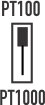
- Select the appropriate sensor type using the DIP switch.
- Set the DIP switch to PT100 when using PT100 sensors.
- Set the DIP switch to PT1000 when using PT1000 sensors.
- PT100 and PT1000 sensors cannot be used together at the same time. All connected sensors must be the same type selected by the DIP switch.
- Configure the input according to the selected sensor type.
- Read the measured temperature.
NORVI X-T4 – 2-Wire NTC Thermistor #
The NORVI X-T4 is a 4-channel NTC thermistor temperature input module. It reads 4 sensor inputs and supports 2-wire NTC thermistors for cost-effective temperature sensing.
A. Sensor wiring #
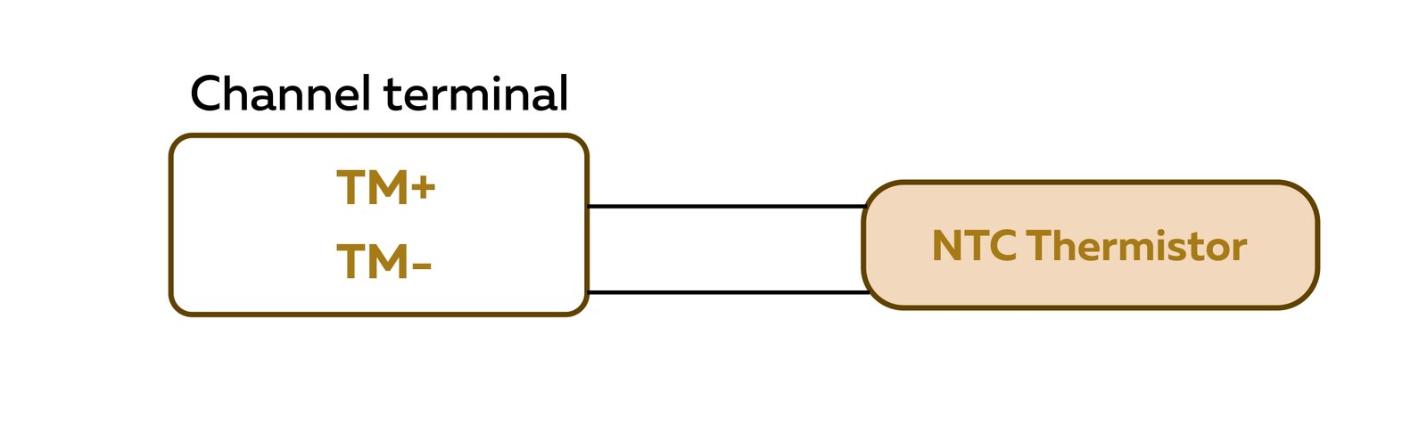
For a 2-wire NTC sensor, connect the two sensor wires to the corresponding input terminals of Channel 1–4. The NTC sensor is non-polarized, so either wire can be connected to either terminal. Ensure that the sensor is connected to the correct channel and terminals.
B. Sensor configuration #
- Connect the X-T4 expansion module to the appropriate expansion port on the NORVI X CPU.
- Connect the NTC thermistor. Connect the 2-wire NTC thermistor to the selected input channel. Since the NTC is non-polarized, wires can be swapped within the same channel.
- Configure the thermistor parameters such as the NTC resistance value and temperature parameters, according to the sensor and specifications.
- Read the temperature value from the corresponding X-T4 input channel after completing the configuration.
Software / Programming #
Set Up → Configure → Upload → Monitor → Verify
- Arduino IDE Setup
Configure the board and communication port:
- Tools → Board → ESP32 Arduino → ESP32S3 Dev Module
- Tools → Port → Select the corresponding COM/serial port
Under the Tools menu, configure the following settings:
| Setting | Selection |
|---|---|
| USB CDC On Boot | Enabled |
| Flash Size | 16MB (128Mb) |
| PSRAM | QSPI PSRAM |
- Required Libraries
Install the libraries required for the NORVI X CPU and temperature module.
- Wire
- SPI
- TFT_eSPI
- CST816S
- Adafruit_ADS1X15
- Free_Fonts
- Upload the Example Code
Connect the NORVI X CPU via USB, select the correct COM port, and upload the program.
Testing the Temperature Sensor #
Test 1 – Room temperature #
- Connect sensor
- Read temperature
- Record value
Test 2 – Change the temperature #
- Warm the sensor carefully
- Observe the temperature increase
- Compare the readings
Test 3 – Multiple sensors #
- Connect sensors to several channels
- Display each channel separately.
Troubleshooting #
| Module | Error / Symptom | Possible Cause | Solution |
|---|---|---|---|
| X-RTD4 | Reading pinned at fault/max value | Open circuit – disconnected sensor or broken lead | Check continuity with multimeter; reseat terminals; replace probe |
| Reading pinned at 0 °C / short fault | RTD+ and RTD – shorted together | Inspect for pinched/bridged leads; confirm terminals aren’t touching | |
| Reading slightly high | Lead resistance (2-wire) | Shorten cable / use 2 wire | |
| Reading way off | PT100/PT1000 mismatch | Correct sensor type setting | |
| Noisy reading | Near AC/relay/motor wiring | Reroute, use shielded cable | |
| X-T4 | Extreme low reading | Open circuit | Check continuity, reseat terminals |
| Extreme high / 0 Ω | Leads shorted | Inspect wiring | |
| Reading offset | Wrong Beta value | Use correct datasheet value | |
| Slow drift | Self-heating / loose contact | Check excitation, tighten terminals | |
| No response to temp change | Faulty sensor or wrong channel | Swap sensor, verify channel |
Comparison: X-RTD4 vs X-T4 #
A final comparison would help users choose the appropriate module.
| Feature | X-RTD4 | X-T4 |
|---|---|---|
| Sensor | PT100 / PT1000 | NTC Thermistor (10kΩ) |
| Sensor technology | RTD | Thermistor |
| Connection | 2-wire | 2-wire |
| Inputs | 4 | 4 |
| Typical use | Industrial temperature measurement | General temperature sensing |