
Introduction #
Home Assistant is an open-source platform for monitoring and controlling devices. ESPHome lets you describe an ESP32 device in a short YAML file, then builds the firmware, handles Wi-Fi, over-the-air updates and the Home Assistant link for you. The NORVI X is a modular industrial controller. With ESPHome, its buttons, digital inputs, relays and 4-20 mA inputs appear in Home Assistant as ordinary entities you can chart, log and automate.
This tutorial configures the NORVI X-CPU-ESPS3-X1 with the X-DI4 (digital inputs), X-R4 (relays) and X-AI4 (4-20 mA inputs). You flash a minimal config first, add one module at a time, then combine them into a single firmware.
What you will need
- NORVI X-CPU-ESPS3-X1 (V2, N16R2) with X-DI4, X-R4 and X-AI4 modules
- 24 V DC regulated supply, 1 A or higher, and a USB cable
- A computer with ESPHome Device Builder, and Home Assistant on the same network
- A switch or 24 V source, a multimeter or low-voltage load, and a 4-20 mA source for testing
System Architecture #
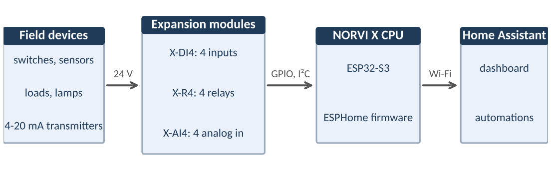
Field signals enter the expansion modules, the ESP32-S3 reads them, and the ESPHome firmware publishes them to Home Assistant over Wi-Fi.
Hardware and address map #
| Part | Interface | Pins / address and notes |
|---|---|---|
| NORVI X-CPU-ESPS3-X1 | I²C bus | SDA IO8, SCL IO9. On-board PCA9536 at 0x41: buttons on P0 and P3, RUN LED on P2, ERROR LED on P1. Also seen in the scan: 0x15 touch, 0x68 RTC, 0x75 PCA9539 |
| NORVI X-DI4 | Direct GPIO | IN1 = IO5, IN2 = IO6, IN3 = IO7, IN4 = IO10; isolated 24 V inputs, shared DCOM |
| NORVI X-R4 | I²C (PCA9538) | Address 0x73 with DIP 1 and 2 OFF (range 0x70 to 0x73); relays on pins 0 to 3; reset line on IO21 |
| NORVI X-AI4 | I²C (ADS1115) | Address 0x49 with DIP 1 ON (options 0x48, 0x4A, 0x4B); 4 channels, 4-20 mA |
Hardware and Wiring #
- Power off the whole system before attaching or removing any module.
- Mount the modules on the DIN rail beside the CPU and seat each one firmly on the expansion bus.
- Check the DIP switches: X-R4 DIP 1 and 2 OFF (0x73), X-AI4 DIP 1 ON and the rest OFF (0x49).
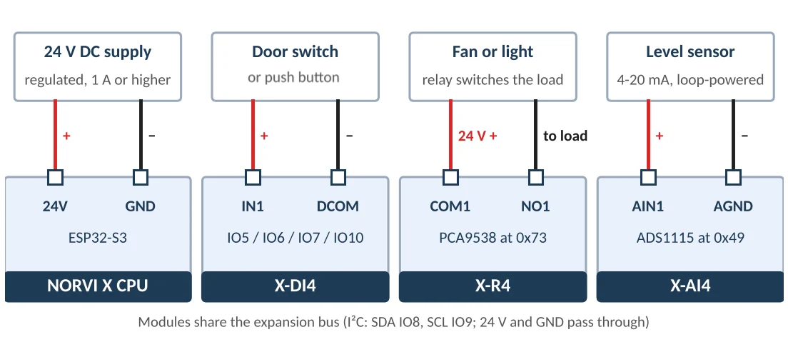
- Wire the field side as in the table below, then connect the 24 V supply to the CPU and power on.
| Module | Wiring |
|---|---|
| X-DI4 | positive through a switch to INx, and negative to DCOM. OFF is below 5 V, ON is above 15 V. |
| X-R4 | Each relay is a normally-open contact: supply to COM, load between NO and the supply return. Rated 5 A at 250 V AC or 30 V DC. |
| X-AI4 | Connect the 4-20 mA signal between AINx and AGND. Keep every channel within 0 to 20 mA. |
Set Up ESPHome and Home Assistant #
- In Home Assistant open Settings > Add-ons > Add-on Store, install ESPHome Device Builder, click Start and switch on Show in sidebar. (This needs Home Assistant OS or Supervised; other installs run ESPHome separately.)
- Click + New Device, name it
norvi-xand choose ESP32-S3. The wizard shows an encryption key: copy it now. You can see it again later under Edit, in theapi:section. - Click Secrets and edit the three values in the table below, replacing the example text with your own. Keep the quotes.
- Click Edit on the new device card, replace its YAML with the base config below, then click Save.
- To use the module files from Section 6, copy
norvi-x-cpu-esps3-x1.yaml,norvi-x-di4.yaml,norvi-x-r4.yamlandnorvi-x-ai4.yamlinto the same esphome folder, using the File editor or Samba share add-on. For the first flash the base config alone is enough. - Click Install > Plug into this computer (Chrome or Edge, board connected by USB). If that option fails, which is common when Home Assistant is opened over plain http, choose Manual download, save the factory image and flash it at
web.esphome.io. If no port appears, hold BOOT while pressing RESET. - After the first boot, the board appears under Settings > Devices & Services as Discovered. Click Configure and paste the encryption key.
- Later changes install wirelessly: edit the YAML, then click Install > Wirelessly.
Values you must edit. These are the only lines you change; the rest of the code stays as it is.
| Secret | What to enter | Where to get it |
|---|---|---|
| wifi_ssid | Name of your Wi-Fi network, in quotes. The Home Assistant computer and the NORVI X must join this same 2.4 GHz network. | Your router label, or the Wi-Fi name your PC is connected to |
| wifi_password | Password of that same Wi-Fi network, in quotes | Your router label or Wi-Fi settings |
| api_encryption_key | A 32-byte base64 key, in quotes. You paste the same key into Home Assistant in step 7. | Copy it from the New Device wizard, or from the api: section under Edit. Or generate one at esphome.io/components/api |
Base config. Every file in this tutorial starts with it. psram: mode: quad matches the N16R2 board, and scan: true prints the I²C devices at boot.
esphome:
name: norvi-x
esp32:
board: esp32-s3-devkitc-1
variant: esp32s3
flash_size: 16MB
framework:
type: esp-idf
psram:
mode: quad
logger:
hardware_uart: USB_SERIAL_JTAG | api:
encryption:
key: !secret api_encryption_key
ota:
- platform: esphome
wifi:
ssid: !secret wifi_ssid
password: !secret wifi_password
i2c:
sda: GPIO8
scl: GPIO9
scan: true |
Configure Each Module #
Each module is a separate file in the example repository. The excerpts below show one channel each; the full files repeat the pattern for every channel.
On-board buttons and LEDs #
| The PCA9536 has the same registers as the PCA9554, so ESPHome’s pca9554 component drives it. Buttons read low when pressed, so they use inverted: true. The LEDs are active low, so they also use inverted: true; without it, ON turns the LED off. | pca9554:
- id: pca9536_io
address: 0x41
binary_sensor:
- platform: gpio
name: "Button 1"
pin: {pca9554: pca9536_io, number: 0,
mode: INPUT, inverted: true}
switch:
- platform: gpio
name: "RUN LED"
restore_mode: ALWAYS_OFF
pin: {pca9554: pca9536_io, number: 2,
mode: OUTPUT, inverted: true} |
X-DI4 digital inputs #
| The inputs go straight to the ESP32 GPIO, so no bus is needed. di_inverted sets the polarity. Apply 24 V to IN1; if Home Assistant shows OFF, set it to “false”. delayed_on and delayed_off filter contact bounce. Remove them for fast pulses. | substitutions:
di_inverted: "true"
debounce: 20ms
binary_sensor:
- platform: gpio
name: "DI4 Input 1"
pin:
number: GPIO5
mode: INPUT
inverted: ${di_inverted}
filters:
- delayed_on: ${debounce}
- delayed_off: ${debounce} |
X-R4 relays #
| The PCA9538 reset pin is wired to IO21. Holding it high lets the module appear in the I²C scan; without it the R4 may be missing at 0x73. setup_priority makes that switch start before the expander. restore_mode: ALWAYS_OFF keeps all relays open after a reboot. | switch:
- platform: gpio # reset line, kept high
id: pca_reset
internal: true
pin: GPIO21
restore_mode: ALWAYS_ON
setup_priority: 2000
- platform: gpio
name: "R4 Relay 1"
restore_mode: ALWAYS_OFF
pin: {pca9554: pca9538_relays,
number: 0, mode: OUTPUT}
pca9554:
- id: pca9538_relays
address: 0x73 |
X-AI4 analog inputs #
| AIN1 to AIN4 map to ADS1115 inputs A0_GND to A3_GND; gain: 2.048 covers 20 mA. multiply: 10 turns volts into mA (5 Ω shunt, ×20 amplifier). This factor is inferred from the block diagram, so confirm it with a known current. calibrate_linear maps 4 to 20 mA onto 0 to 10; change the second numbers for your sensor range. The empty unit and class remove the default “V” in Home Assistant. | ads1115:
- id: ai4_adc
address: 0x49
sensor:
- platform: ads1115
ads1115_id: ai4_adc
name: "AI4 Channel 1"
multiplexer: A0_GND
gain: 2.048
unit_of_measurement: ""
device_class: ""
filters:
- multiply: 10 # volts -> mA
- calibrate_linear:
- 4.0 -> 0.0
- 20.0 -> 10.0 |
Combine the Modules #
A NORVI X runs one firmware at a time, so combine the four files with ESPHome packages. The main file is norvi-x-combined.yaml; keep all files in one folder; settings in the main file override the included ones, and lists such as switch and sensor are joined.
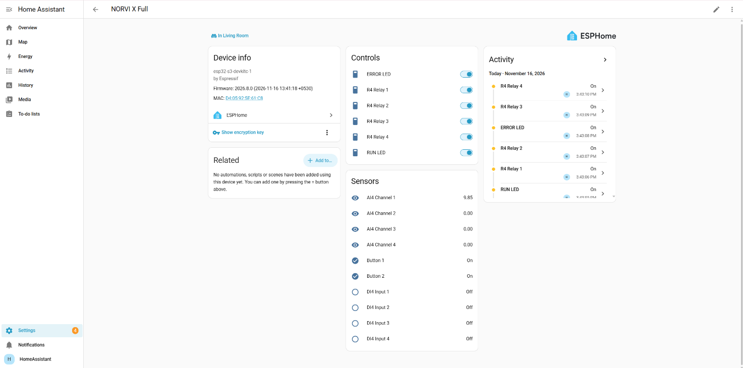
| After the install, the log should list 0x15, 0x41, 0x49, 0x68, 0x73 and 0x75 in the I²C scan. Home Assistant then shows 16 entities: 2 buttons, 4 DI4 inputs, 2 LEDs, 4 relays and 4 AI4 channels. | substitutions:
name: norvi-x-full
friendly_name: "NORVI X Full"
packages:
onboard: !include norvi-x-cpu-esps3-x1.yaml
di4: !include norvi-x-di4.yaml
r4: !include norvi-x-r4.yaml
ai4: !include norvi-x-ai4.yaml |
Commissioning and Test #
| Test | Pass condition |
|---|---|
| Flash and OTA | Device boots, joins Wi-Fi, appears in Home Assistant, and a wireless update succeeds |
| Buttons and LEDs | Each button changes state when pressed; each LED lights when its switch is ON |
| X-DI4 | Applying and removing 24 V on each input flips it ON and OFF with no false triggers |
| X-R4 | Each relay clicks and the contact changes, checked with a multimeter first; all are OFF after a reboot |
| X-AI4 | With a 4-20 mA source, 4 mA reads 0.00 and 20 mA reads 10.00 on every channel |
Troubleshooting #
| Symptom | Likely cause | Remedy |
|---|---|---|
| R4 missing from the I²C scan | PCA9538 held in reset, or module not seated | Hold IO21 high as in 5.3; power off and reseat the module |
| AI4 values Unknown, log says ads1115 FAILED | X-AI4 not seated, wrong DIP address or weak supply | Reseat it, set DIP 1 ON for 0x49, use a regulated 24 V, 1 A supply |
| DI4 inputs read inverted | Polarity | Set di_inverted to “false” |
| One DI4 input flickers | Weak signal, noise or loose DCOM | Check the voltage is above 15 V and the wiring; raise the debounce |
| LED lights when OFF | LEDs are active low | Keep inverted: true |
| 4-Way Handshake Timeout | Wrong Wi-Fi password or weak signal | Check the secrets, attach the antenna, move closer to the router |
| No port or flashing fails | Charge-only cable, no driver, or browser blocks USB | Use a data cable, hold BOOT and press RESET, or flash the factory image at web.esphome.io |
| Device not discovered | Different network, 5 GHz Wi-Fi or wrong key | Same 2.4 GHz network; add it by IP under Devices & Services > ESPHome |
Safety. Disconnect all power before wiring and let a qualified electrician install the system. Test relays with a low-voltage load before switching mains.
Example Use Cases #
| Module | Typical uses |
|---|---|
| On-board buttons and LEDs | Local start/stop button; RUN and ERROR LEDs as status lights driven from Home Assistant. |
| X-DI4 inputs | Door or window contact, push button, float switch, limit switch, flow switch. |
| X-R4 relays | Switch a fan, light, pump, heater or door lock (5 A per relay; use a contactor for larger loads). |
| X-AI4 inputs | 4-20 mA tank level, pressure, temperature or flow transmitters. |
| Combined | Tank control: AI4 level sensor starts the R4 pump below 20 %, a DI4 float switch raises a dry-run alarm. |
Conclusion #
The NORVI X and its DI4, R4 and AI4 modules now run under ESPHome as native Home Assistant entities. Next steps: the DS3231 clock, RS-485 Modbus, or scaling the AI4 to a real unit such as bar.
Resources
CPU guide: norvi.io/docs/norvi-x-cpu-esps3-x1-user-guide/ | X-AI4: norvi.io/docs/norvi-x-ai4-datasheet/ | X-R4: norvi.io/docs/norvi-x-r4-datasheet/
ESPHome: esphome.io | Home Assistant: home-assistant.io | norvi-x-esphome repository
Explore technical files and available resources.
View on GitHub ↗


