
NORVI X is a next-generation modular industrial controller designed to power smart automation and IoT solutions. Built around a powerful CPU module and a range of plug-and-play expansion modules, the platform scales from a handful of I/O points up to 200 inputs and outputs, giving system integrators, OEMs, and industrial engineers a flexible foundation for automation, remote monitoring, and data acquisition projects.
The NORVI CPU-ESPS3-X1 is the base CPU module in the NORVI X range. It combines an ESP32-S3 processor with a built-in touch display, Ethernet, RS-485, Wi-Fi, and Bluetooth connectivity, and is designed to pair with NORVI X expansion modules to build a complete industrial control system on a DIN rail.
This guide covers everything needed to confidently install, configure, and deploy the module – including safety requirements, hardware specifications, GPIO and wiring references, Arduino IDE setup, diagnostic test code, expansion module integration, supported communication protocols, and troubleshooting.
Key Features #
- Based on the ESP32-S3-WROOM-1U-N16R2 (16 MB Flash, 512 KB SRAM, 2 MB PSRAM)
- 2.0″ TFT SPI display (ST7789 driver)
- Built-in RS-485 communication with an SN65HVD72DGKR half-duplex transceiver and automatic direction control
- Built-in Ethernet communication
- Wi-Fi 2.4 GHz and Bluetooth connectivity
- DS3231 real-time clock (RTC)
- MicroSD card support (SPI interface)
- DIN-rail mountable enclosure with pluggable terminals
- Scales up to 200 I/O points via NORVI X expansion modules
- CE / EMC compliant (EN 61131-2:2007, EN 61010-1:2010+A1:2019, EN IEC 61010-2-201:2018, 2014/30/EU)
Supported Expansion Modules #
An expansion module from NORVI Controllers must be used to add process I/O to the CPU module. The following expansion module families are currently available:
| Category | Examples |
|---|---|
| Digital Input | X-DI4 (GPIO), X-DI8 / X-DI16 (I²C) – 12–24V DC |
| Relay Output | X-R4, X-R8 (I²C, 5A relay) |
| Transistor Output | X-Q4 (GPIO), X-Q8 / X-Q16 (I²C) – 0.5A/ch |
| Analog Input | X-AV4 0–10V (I²C, 16-bit ADC), X-AI4 4–20mA (I²C, 16-bit ADC) |
| Digital/AC Input | X-DA8 (I²C) – 110/230V AC |
| Analog Output | X-AQ4 0–10V / 4–20mA (I²C) |
| Sensor | X-RTD4 (Pt100/Pt1000) |
| Comms | X-UART-IO – RS-485 / RS-232 / UART |
Note: When selecting expansion modules, refer to the NORVI X Mixing Guide to ensure the selected modules are compatible.
Safety Information #
Warning: Disconnect all power sources before installing, wiring, or servicing the NORVI CPU-ESPS3-X1. Failure to do so may result in electric shock or damage to the equipment.
- Install and wire this device only if you are a qualified electrician or trained technician familiar with industrial control equipment.
- Use a regulated 24 V DC power source rated at least 1 A. Do not exceed the rated supply voltage.
- Mount the unit on a DIN rail inside a suitably rated enclosure (the module has an IP20 protection rating and is not designed for direct outdoor or wash-down exposure).
- Keep the operating environment within –40°C to +85°C and avoid condensing humidity.
- Do not connect or disconnect expansion modules or communication wiring while the system is powered.
- Ensure adequate spacing around the unit and expansion modules for ventilation and wiring access.
- Follow all local and national electrical codes applicable to industrial control panel wiring.
Technical Specifications #
Peripherals #
MicroSD Card (SPI) #
| Interface | SPI |
| CS | IO42 |
| MISO / MOSI / SCLK | IO13 / IO11 / IO12 |
| Card detect | Not connected |
Display (ST7789 TFT) #
| MISO / MOSI / SCLK | IO13 / IO11 / IO12 |
| Display CS | IO45 |
| Display reset | IO47 |
| Display DC | IO46 |
| Touch SCL / SDA | IO9 / IO8 |
RS-485 #
| Transceiver | SN65HVD72DGKR |
| Mode | Half-duplex |
| Unit load | 1/4 |
| Direction control | Automatic |
| TX / RX pins | IO15 / IO16 |
Hardware Layout & GPIO Map #
The table below lists the GPIO pins reserved for on-board CPU functions. Pins not listed here are broken out to the 50-pin expansion port (Section 6) for use by expansion modules or custom wiring.
| GPIO | CPU Function | Expansion Port |
|---|---|---|
| 0 | BOOT Button | NC |
| 1 | SCSN – Ethernet | IO1 |
| 2 | RSTN – Ethernet | IO2 |
| 4 | INTN – Ethernet | IO4 |
| 8 | SDA | SDA |
| 9 | SCL | SCL |
| 11 | MOSI | MOSI |
| 12 | SCLK | SCLK |
| 13 | MISO | MISO |
| 15 | RS485 – TX | IO15 |
| 16 | RS485 – RX | IO16 |
| 19 | USB – DN | D_N |
| 20 | USB – DP | D_P |
| 38 | PCA9536 – RESET | RST_PCA |
| 42 | SD CARD – CS | NC |
| 45 | CS – TFT DISPLAY | NC |
| 46 | DC – TFT DISPLAY | NC |
| 47 | RESET – TFT DISPLAY | NC |
| 48 | INTERRUPT – TOUCH PANEL | NC |
Note: Some of the GPIOs are not available on the N16R8 version; they are supported only on the standard version.
Wiring Guide #
GPIO pin assignments for every signal referenced below are listed once in Section 5 (Hardware Layout & GPIO Map) ; this section covers how to physically connect each interface, not the pin numbers themselves.
Power Connection #
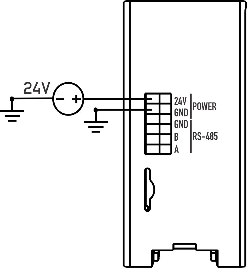
- Use a regulated 24 V DC power supply rated at 1 A or higher.
- Connect 24 V and GND to the pluggable power terminals as marked on the enclosure.
- Double-check polarity before applying power.
RS-485 #
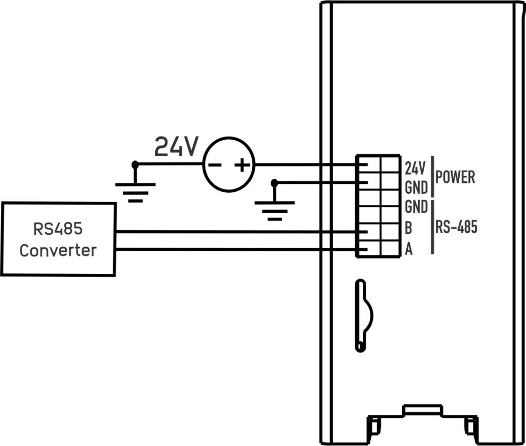
The RS-485 port uses a 3.3V SN65HVD72DGKR transceiver in half-duplex mode with automatic direction control, so no manual DE/RE handling is required in firmware.
- Connect the A and B terminals to the corresponding A/B (or D+/D–) terminals on the RS-485 field device or upstream Modbus RTU master.
- Connect a common GND reference between devices where the network spans separate power supplies.
- Use a 120 Ω termination resistor at both ends of long RS-485 runs per standard EIA-485 practice.
Note: The on-board SN65HVD72DGKR transceiver operates on 3.3 V logic and uses automatic flow control (hardware-driven direction switching) on this board. Some example sketches (such as the Modbus RTU application guide) instead drive the RS-485 flow-control GPIO manually – HIGH before transmitting, LOW to return to listen mode (see Section 5 for the exact pin) – so check which mode your firmware uses before wiring a multi-drop network.
Ethernet #
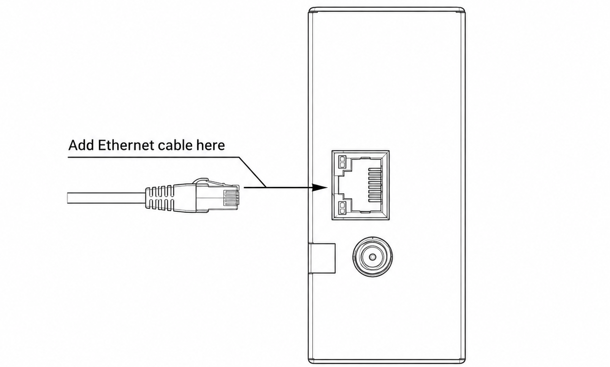
Connect a standard RJ45 Ethernet cable from the module to your network switch or router. The onboard Ethernet controller is dedicated hardware, independent of the Wi-Fi radio, so both interfaces can be used simultaneously if required by your application.
Connecting an Expansion Module #
Expansion modules (digital input, relay output, analog I/O, etc.) connect to the CPU module via the shared expansion bus or through direct GPIO access, and are wired to field devices at their dedicated terminals. The steps below use the 4-channel Digital Input module (X-DI4) as a worked example – the same pattern applies to other expansion module types.
- Power off the system, then mount the expansion module on the DIN rail next to the CPU module and seat it onto the expansion bus connector.
- Wire your field signals (e.g. door contacts, limit switches, push buttons) to the module’s INPUT 1-4 terminals. Confirm the signal is within the module’s supported input range (24V DC for the X-DI4).
- Power the system back on.
- Upload the module’s test sketch to confirm each channel reads correctly on the TFT display or Serial Monitor before wiring it into your final control logic.
Expansion Port (50-pin) #
Expansion modules connect via the 50-pin expansion bus.
| PIN INDEX | Purpose | GPIO | SOURCE |
|---|---|---|---|
| 1 | MOSI | IO11 | ESP32-S3 |
| 2 | MISO | IO13 | |
| 3 | SCLK | IO12 | |
| 4 | GND | — | |
| 5 | SCL | IO9 | |
| 6 | SDA | IO8 | |
| 7 | GND | — | |
| 8 | RX1 | IO18 | |
| 9 | TX1 | IO17 | |
| 10 | GND | — | |
| 11 | D+ | IO20 | |
| 12 | D- | IO19 | |
| 13 | GND | — | |
| 14 | CS1 | P1_0 | PCA9539 I2C Address 0x75 |
| 15 | CS2 | P0_7 | |
| 16 | CS3 | P0_6 | |
| 17 | CS4 | P0_5 | |
| 18 | IO1 | IO1 | ESP32-S3 |
| 19 | IO2 | IO2 | |
| 20 | IO4 | IO4 | |
| 21 | IO5 | IO5 | |
| 22 | IO6 | IO6 | |
| 23 | IO7 | IO7 | |
| 24 | IO10 | IO10 | |
| 25 | IO11 | IO35 | |
| 26 | IO12 | IO41 | |
| 27 | IO13 | IO37 | |
| 28 | IO14 | IO14 | |
| 29 | RS485_TX | IO15 | |
| 30 | GND | — | |
| 31 | GND | — | |
| 32 | RS485_RX | IO16 | |
| 33 | P1_1 | P1_1 | PCA9539 I2C Address 0x75 |
| 34 | P1_2 | P1_2 | |
| 35 | IO21 | IO21 | ESP32-S3 |
| 36 | GND | — | |
| 37 | GND | — | |
| 38 | P1_3 | P1_3 | PCA9539 I2C Address 0x75 |
| 39 | P1_4 | P1_4 | |
| 40 | P1_5 | P1_5 | |
| 41 | IO39 | IO39 | ESP32-S3 |
| 42 | IO40 | IO40 | |
| 43 | NC | — | |
| 44 | NC | — | |
| 45 | NC | — | |
| 46 | GND | — | |
| 47 | 5V | 5V | |
| 48 | GND | GND | |
| 49 | 24V | 24V | |
| 50 | 24V | 24V |
Software Setup (Arduino IDE) #
The NORVI CPU-ESPS3-X1 is programmed using the Arduino IDE with the ESP32 board package. Firmware examples and required libraries are maintained in the NORVI GitHub repository.
Board Configuration #
- Board: ESP32S3 Dev Module
- Recommended Arduino IDE version: 1.8.19
Setup Steps #
1. Install the Arduino IDE and add ESP32 board support via Tools → Board → Boards Manager.
2. Connect the NORVI CPU ESPS3-X1 to your computer via the USB interface.
3. Under Tools → Board, select ESP32S3 Dev Module, and under Tools → Port, select the corresponding COM/serial port.
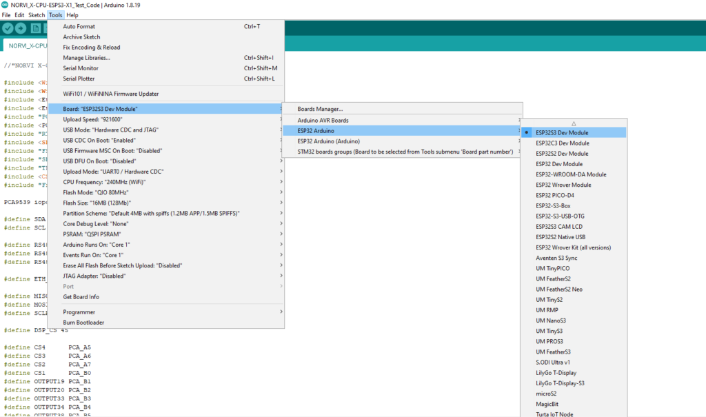
4. Configure the required settings under the Tools menu according to your setup. Refer to the Board Settings Configuration section for the complete list of recommended settings.
5. Under Tools → USB CDC On Boot, select Enabled, under Tools → Flash Size, select 16MB (128Mb), and under Tools → PSRAM, select QSPI PSRAM.
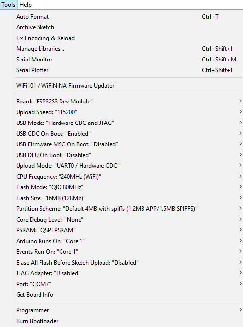
| Setting | Value |
|---|---|
| Board | ESP32S3 Dev Module |
| Upload Speed | 115200 |
| USB Mode | Hardware CDC and JTAG |
| USB CDC On Boot | Enabled |
| USB Firmware MSC On Boot | Disabled |
| USB DFU On Boot | Disabled |
| Upload Mode | UART0 / Hardware CDC |
| CPU Frequency | 240MHz (WiFi) |
| Flash Mode | QIO 80MHz |
| Flash Size | 16MB (128Mb) |
| Partition Scheme | Default 4MB with spiffs (1.2MB APP/1.5MB SPIFFS) |
| Core Debug Level | None |
| PSRAM | QSPI PSRAM |
| Arduino Runs On | Core 1 |
| Events Run On | Core 1 |
| Erase All Flash Before Sketch Upload | Disabled |
| JTAG Adapter | Disabled |
| Port | Select the COM/serial port corresponding to your connected board |
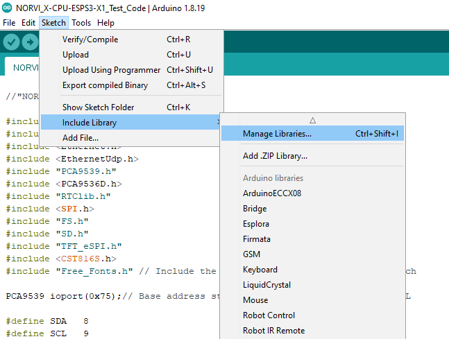
6. Install the required libraries via Sketch → Include Library → Manage Libraries, searching for each library named on GitHub.
7. Open the example sketch for your application from the NORVI GitHub repository, verify the board/port selection, and click Upload.
Test Code Examples #
NORVI Controllers publishes an official diagnostic sketch for the NORVI X-CPU-ESPS3-X1 that exercises every on-board peripheral in one run. The excerpts below are taken directly from that sketch and cover the checks most useful for verifying a fresh installation. The full sketch is available in the NORVI-X-Version-02 GitHub repository.
Required Libraries #
Install these via Arduino IDE → Sketch → Include Library → Manage Libraries before compiling any of the examples below:
- Wire
- WiFi
- Ethernet
- SPI
- PCA9539
- PCA9536D
- RTClib (DS3231 RTC)
- TFT_eSPI
- CST816S
I2C Bus Scan #
Run this first after wiring – it confirms every on-board I²C peripheral is being detected before you test anything else.
void I2C_SCAN() {
  byte error, address;
  int deviceCount = 0;

  Serial.println("Scanning...");

  for (address = 1; address < 127; address++) {
    Wire.beginTransmission(address);
    error = Wire.endTransmission();

    if (error == 0) {
      Serial.print("I2C device found at address 0x");
      if (address < 16) {
        Serial.print("0");
      }
      Serial.print(address, HEX);
      Serial.println("  !");

      deviceCount++;
      delay(1);  // Wait for a moment to avoid overloading the I2C bus
    }
    else if (error == 4) {
      Serial.print("Unknown error at address 0x");
      if (address < 16) {
        Serial.print("0");
      }
      Serial.println(address, HEX);
    }
  }

  if (deviceCount == 0) {
    Serial.println("No I2C devices found\n");
  }
  else {
    Serial.println("Scanning complete\n");
  }
}
Expected devices on a CPU module:
| 0x15 | CST816S touch controller |
| 0x41 | PCA9536 I/O expander (buttons PB1/PB3 and status LEDs) |
| 0x68 | DS3231 real-time clock |
| 0x75 | PCA9539 base I/O expander |
RS-485 Loopback Test #
Connect an RS-485-to-USB converter to the module’s A/B terminals and the USB end to a PC. Open a terminal program with matching baud rate and settings to view the live data exchange and confirm the module’s RS-485 interface is working.
#define RS485_RXD 16
#define RS485_TXD 15

Serial2.begin(115200, SERIAL_8N1, RS485_RXD, RS485_TXD);

Serial2.println("RS485 01 SUCCESS");

while (Serial2.available()) {
  char c = Serial2.read();
  Serial.write(c);
}
Wi-Fi Access Point Test #
Brings the module up as its own Wi-Fi access point (SSID = the module’s MAC address, password 12345678) – useful for confirming the radio and connecting a phone or laptop for initial commissioning before pointing the device at a production network.
void wifi_test(){
  Serial.println("");
  String str_macAddress;
  byte mac[6];

  WiFi.macAddress(mac);

   str_macAddress = (String(mac[0] >> 4,  HEX) + String(mac[0] & 0x0F, HEX)) + (":") +
                   (String(mac[1] >> 4,  HEX) + String(mac[1] & 0x0F, HEX)) + (":") +
                   (String(mac[2] >> 4,  HEX) + String(mac[2] & 0x0F, HEX)) + (":") +
                   (String(mac[3] >> 4,  HEX) + String(mac[3] & 0x0F, HEX)) + (":") +
                   (String(mac[4] >> 4,  HEX) + String(mac[4] & 0x0F, HEX)) + (":") +
                   (String(mac[5] >> 4,  HEX) + String(mac[5] & 0x0F, HEX));
  str_macAddress.toUpperCase();

  Serial.println("MAC Address: " + str_macAddress);

  String ssid =  str_macAddress;
  const char* password = "12345678";

  Serial.println("Setting up the Wi-Fi Access Point...");
  WiFi.softAP(ssid.c_str(), password);

  IPAddress IP = WiFi.softAPIP();
  Serial.print("Access Point IP address: ");
  Serial.println(IP);

  Serial.print("Access Point SSID: ");
  Serial.println(ssid);

  Serial.println("Wi-Fi Access Point is active!");
  Serial.println("");
}
Validating the Full Test Sketch #
When the complete official test sketch runs successfully, you should see:
- Display & touch – the TFT initializes and shows “NORVI CONTROLLERS”; touching the screen prints gesture, point count, and X/Y coordinates.
- Ethernet – with a cable connected and internet access available, the Serial Monitor prints the UTC time retrieved via NTP.
- RS-485 – data sent out the A/B terminals is visible on an RS-485-to-USB converter connected to a PC.
- SD card – card type and size are printed if a microSD card is inserted.
- RTC – the current date/time is printed; if the RTC loses power, the sketch sets it from the compile-time clock.
Communication Protocols #
- Modbus RTU
- Modbus TCP
- MQTT / MQTTS
- HTTP / HTTPS
- Bluetooth Low Energy (BLE) – GATT
Modbus RTU is a serial communication protocol used to exchange data between industrial devices over RS-485. Modbus TCP enables Modbus communication over Ethernet and TCP/IP networks. MQTT/MQTTS provides lightweight messaging for monitoring, data reporting, and IoT connectivity. HTTP/HTTPS supports web-based data exchange, configuration, and API integration. Bluetooth Low Energy (BLE) – GATT provides short-range communication for local commissioning, configuration, and device data exchange.
Troubleshooting #
| Symptom | Suggested Action |
|---|---|
| Unit does not power on / RUN indicator off | Verify the 24 V DC supply is present and within tolerance at the terminals; check polarity and supply current rating (≥1 A). |
| Display stays blank after power-up | Confirm that the firmware has been uploaded correctly. Check the TFT_eSPI library version and its internal configuration. Also, verify that PSRAM is set to QSPI PSRAM. |
| Arduino IDE cannot find the board/COM port | Check the USB cable and drivers, confirm ESP32S3 Dev Module is selected, and try a different USB port. |
| Expansion module not detected | Power down and reseat the module on the expansion bus; verify I²C address configuration does not conflict with another installed module. |
| RS-485 communication errors / no response | Check A/B polarity, confirm common GND reference, verify baud rate matches the field device, and confirm termination resistors on long cable runs. |
| Ethernet link not established | Confirm cable and switch port are active; verify the Ethernet controller is initialized in firmware (SCSN on IO1), and check the SPI connection. |
| Device resets unexpectedly under load | Check power supply current headroom, especially when multiple expansion modules or a cellular modem module are attached. |
Support & Resources #
Access NORVI X documentation, firmware resources, product information, and technical support.