
Introduction #
Modbus RTU remains one of the most widely used communication protocols in industrial automation. It is simple, robust, and supported by almost every PLC, sensor, drive, and energy meter on the market. This guide shows how to use a NORVI-X CPU as both a Modbus RTU master and a Modbus RTU slave over an RS-485 line. It covers practical wiring, a clear explanation of the code, and the error handling that separates a quick demo from something you can leave running on a factory floor.
The NORVI-X CPU is an ESP32-S3 based industrial controller with an integrated RS-485 transceiver and an on-board TFT display. Throughout this guide, the display is used to show live communication status, which makes commissioning and troubleshooting far easier than relying on a serial monitor alone. The complete source code is hosted on GitHub and linked in each section, so this document focuses on understanding the logic rather than reproducing long code listings.
By the end of this guide, you should be able to:
- Wire an RS-485 network between NORVI-X devices
- Load the master or slave firmware onto a NORVI-X
- Verify communication on the on-board display
- Adapt the register map to your own application
Featured snippet answer: Modbus RTU is a serial communication protocol used in industrial automation to exchange data between a master device and one or more slave devices over an RS-485 network. The NORVI-X CPU, an ESP32-S3-based industrial controller, can be configured as either a Modbus RTU master or slave using the modbus-esp8266 library.
Modbus Protocol in Brief #
Modbus is a request–response protocol. One device, the master (also called the client), initiates every transaction. One or more slaves (servers) listen on the same bus and reply only when addressed. A single RS-485 network supports one master and up to 247 slaves, each identified by a unique address from 1 to 247..
Table 1. Modbus data model
Data in Modbus is organized into four basic types. Understanding these makes the register maps in later sections straightforward.
| Object Type | Access | Size | Typical Use |
|---|---|---|---|
| Coil | Read / Write | 1 bit | Digital outputs, on/off flags |
| Discrete Input | Read only | 1 bit | Digital inputs, status bits |
| Input Register | Read only | 16 bit | Sensor and measured values |
| Holding Register | Read / Write | 16 bit | Setpoints, configuration, data |
Each request carries a function code that tells the slave what operation to perform. The most common codes are:
- 0x03 — Read Holding Registers
- 0x04 — Read Input Registers
- 0x06 — Write Single Register
- 0x10 — Write Multiple Registers
The examples in this guide use holding registers, which are the most flexible of the four Modbus object types.
RTU Mode and the Data Frame #
Modbus can run over several transports. This guide uses Modbus RTU, the serial variant designed for RS-485 lines. In RTU mode, each message is sent as a compact stream of binary bytes, and every frame ends with a 16-bit Cyclical Redundancy Check (CRC) so the receiver can detect corrupted data.
A typical serial configuration for Modbus RTU is 9600 baud, 8 data bits, no parity, and 1 stop bit (written 9600 8N1). Every device on the same bus must use identical serial settings and a matching baud rate, otherwise communication will fail even though the wiring is correct. The byte format is summarized below.
Table 2. Modbus RTU serial byte format
| Parameter | Value |
|---|---|
| Coding system | 8-bit binary |
| Start bit | 1 |
| Data bits | 8 (least significant bit first) |
| Parity | None (even/odd optional) |
| Stop bit | 1 (2 if no parity) |
| Error check | CRC-16 |
RS-485 on the NORVI-X #
Every NORVI-X device with RS-485 connectivity carries an on-board SN-65 class transceiver whose A and B terminals are brought out to the field connector. On the NORVI-X CPU, the transceiver is wired to the ESP32-S3 hardware UART used as Serial1 or Serial2, with the transmit and receive lines mapped to dedicated GPIOs. Direction is handled automatically by the transceiver, so no separate flow-control (DE/RE) pin needs to be toggled in software.
The RS-485 GPIO assignment used in the example firmware is listed below. If you build on a different NORVI model, confirm the pin mapping against the NORVI RS-485 GPIO allocation table before compiling.
Table 3. NORVI-X CPU RS-485 signal assignment
| Signal | ESP32-S3 GPIO | UART |
|---|---|---|
| RS-485 RXD | 16 | Serial2 |
| RS-485 TXD | 15 | Serial2 |
| Direction control | Automatic (transceiver) | – |
Hardware and Wiring #
To reproduce the setup in this guide, you will need:
- A NORVI-X CPU
- A second Modbus device (a second NORVI-X, a PC running Modbus simulator software with a USB-to-RS-485 converter, or any commercial Modbus slave)
- A twisted-pair cable for the RS-485 line
- A USB cable for programming and power
RS-485 is a two-wire differential bus. Connect A to A and B to B between every device on the network; never cross them. On longer runs, tie the ground references of the devices together with the cable shield or a third conductor to keep both transceivers within their common-mode range.
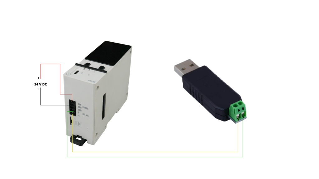
Figure 1. RS-485 connection between the NORVI-X master and a slave device.
Two practical rules keep a bus reliable:
- Wire in a daisy chain, not a star. Long stubs branching off the main line cause reflections.
- Terminate both ends. Fit a 120 Ω termination resistor across A and B at each of the two physical ends of the bus.
Termination and correct grounding matter far more as cable length and baud rate increase.
Table 4. RS-485 terminal connections
| NORVI-X (Master) | Slave Device | Notes |
|---|---|---|
| A | A | Non-inverting line |
| B | B | Inverting line |
| GND | GND | Common reference / shield |
Library Setup #
The example firmware uses the modbus-esp8266 library by Alexander Emelianov, which, despite its name, fully supports the ESP32 and ESP32-S3. Install it from the Arduino Library Manager by searching for “modbus-esp8266”.
Note: Several unrelated libraries also expose a header named ModbusRTU.h. If a different ModbusRTU library is already installed, the compiler may pick the wrong one and fail with errors about a protected constructor or missing begin() and task() methods. Remove any conflicting ModbusRTU library from your Arduino libraries folder and keep only modbus-esp8266.
Library: https://github.com/emelianov/modbus-esp8266
NORVI-X as a Modbus RTU Master #
As the master, the NORVI-X periodically polls a slave, reads a block of holding registers, and shows the results on its display. The full sketch is on GitHub; the sections below explain the parts that matter.
Master source code: NORVI-X Modbus RTU Master (GitHub)
Configuration #
A short block at the top of the sketch defines everything you are likely to change: the RS-485 baud rate, the target slave address, the first register and how many registers to read, and the polling interval. Keeping these together means adapting the code to a new device rarely requires touching the logic below.
#define RS485_BAUD 9600   // must match every device on the bus
#define SLAVE_ID 1        // address of the slave to poll
#define HREG_START 0      // first holding register
#define HREG_COUNT 4      // number of registers to read
#define POLL_MS 500        // poll interval in milliseconds
Initialization #
During setup, the sketch starts Serial2 on the RS-485 pins, hands that port to the Modbus library, and switches the library into master mode. Because the NORVI-X transceiver controls direction automatically, the direction-pin argument is left disabled.
Serial2.begin(RS485_BAUD, SERIAL_8N1, RS485_RXD, RS485_TXD);
mb.begin(&Serial2, RS485_DE); // RS485_DE = -1 -> automatic direction
mb.master();
Polling and Error Handling #
In the main loop, the master issues one read request at a time and waits for the response through a callback. The callback records whether the transaction succeeded and updates the counters shown on the display. If several consecutive requests fail, the master marks the slave as offline; a single successful reply brings it back online. This simple state machine is what makes the link status on the display trustworthy.
if (!txBusy && millis() - lastPoll >= POLL_MS) {
  if (mb.slave() == 0) { // bus is free
    txBusy = true;
    mb.readHreg(SLAVE_ID, HREG_START, hr, HREG_COUNT, onData);
  }
}
mb.task(); // must run every loop iteration
The onData callback increments the poll and error counters, tracks a run of consecutive failures, and flips the online flag accordingly. Handling errors here, rather than ignoring the return value, is the difference between a display that reports reality and one that silently shows stale numbers.
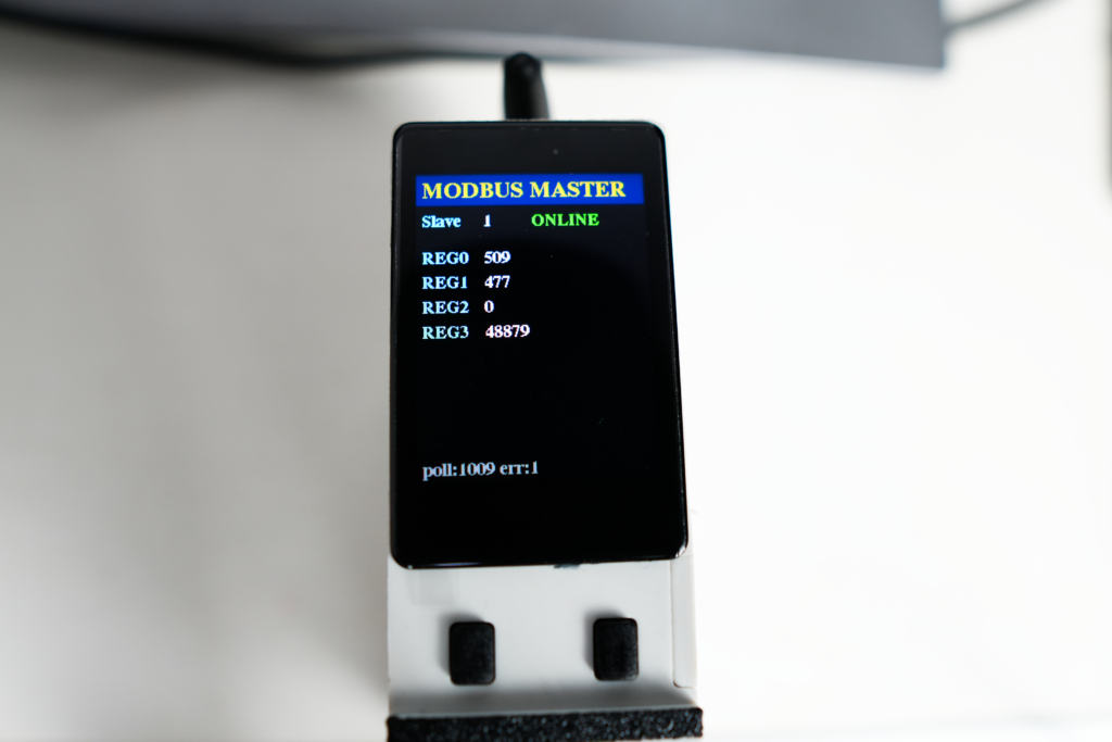
Result #
values, so the screen stays flicker-free. The header shows the mode, the second line shows the slave address and link status, and the register values update live. A small footer keeps a running total of polls and errors, which is useful during commissioning.
NORVI-X as a Modbus RTU Slave #
As a slave, the NORVI-X waits for requests from a master, serves values from its register map, and shows what it is exposing on the display. The full sketch is on GitHub; the key parts follow.
Slave source code: NORVI-X Modbus RTU Slave (GitHub)
Register Map and Initialisation #
The slave is given a fixed address and a small block of holding registers. Each register is created once during setup, after which the master can read or write it. Optional callbacks let the sketch count how many requests it has served, which is shown on the display as confirmation that the master is actually talking to it.
Serial2.begin(RS485_BAUD, SERIAL_8N1, RS485_RXD, RS485_TXD);
mb.begin(&Serial2, RS485_DE);
mb.slave(SLAVE_ID);
for (int i = 0; i < HREG_COUNT; i++) mb.addHreg(i, 0);
Serving Data #
The loop calls the library task on every iteration so incoming frames are answered promptly, then periodically updates the register contents with whatever the device is measuring or producing. In the example, placeholder values are written so the master has something changing to display; in a real deployment, these lines would read analog inputs, digital inputs, or internal state.
mb.task(); // answer incoming requests
mb.Hreg(0, uptimeSeconds); // replace with real sensor / IO values
mb.Hreg(1, analogValue);
mb.Hreg(2, coilState);
Result #
The slave display mirrors the master layout for consistency: a header, the slave address, the register values it is serving, and a footer counting requests served. Seeing that counter rise confirms the two devices are communicating before you connect anything to the field wiring.
Production Notes #
A few habits turn working example code into a dependable field installation:
- Match serial settings everywhere. Baud rate, parity, and stop bits must be identical on every device; a mismatch is the most common cause of a silent bus.
- Verify communication on the display first. Confirm the online status and rising counters before trusting downstream logic or wiring the process.
- Handle timeouts explicitly. Treat a missing reply as an error, count it, and drive an online/offline state rather than assuming every read succeeds.
- Terminate and ground the bus. Fit 120 Ω resistors at both ends and share a ground reference, especially on long runs and higher baud rates.
- Keep the register map documented. Record which register holds which value — it is the interface contract between master and slave.
From RTU to a Gateway #
Because the master already collects data into a structured register array, extending the NORVI-X into a Modbus gateway is a natural next step. The same polled values can be forwarded over Modbus TCP, MQTT, or a cellular link, turning the controller into a bridge between a legacy RS-485 network and a modern Industrial IoT platform. The wiring and RTU logic in this guide remain unchanged; only the outbound transport is added.
Troubleshooting #
Table 5. Common Modbus RTU issues and remedies
| Symptom | Likely Cause | Remedy |
|---|---|---|
| No response / stays OFFLINE | A and B swapped, or baud mismatch | Swap A/B; confirm identical serial settings |
| Intermittent errors | Missing termination or noise | Fit 120 Ω at both ends; share ground |
| Wrong values | Register offset or count mismatch | Align start address and register count |
| Compile errors on ModbusRTU | Conflicting library installed | Keep only modbus-esp8266 |
If your controller shares its RS-485 pins with the USB serial port, avoid using serial print for debugging and rely on the on-board display instead, exactly as the examples in this guide do.
Frequently Asked Questions #
Modbus RTU is a request–response serial communication protocol used in industrial automation, where a master device polls one or more slave devices over an RS-485 bus, with each frame protected by a 16-bit CRC.
A single RS-485 network supports one master and up to 247 slaves, each identified by a unique address from 1 to 247.
A typical Modbus RTU configuration is 9600 baud, 8 data bits, no parity, and 1 stop bit, written as 9600 8N1. Every device on the bus must use identical serial settings.
The example firmware uses the modbus-esp8266 library by Alexander Emelianov, which despite its name fully supports the ESP32 and ESP32-S3 used in the NORVI-X CPU.
The most common causes are the A and B RS-485 lines being swapped or a mismatch in baud rate or serial settings between devices. Confirm identical serial settings on every device and check the A/B wiring.
es. Fit a 120 Ω termination resistor across A and B at each of the two physical ends of the bus, and share a ground reference between devices — this becomes more important as cable length and baud rate increase.