
What is NORVI XN-MAIN? #
NORVI XN-MAIN is an industrial modular controller built around the ESP32-S3-WROOM-1U-N16R2. It is designed for DIN-rail mounting in control panels and is part of the NORVI X modular ecosystem.
Unlike a conventional single-processor design, XN-MAIN uses two controllers with distinct roles:
- Main Application Controller (ESP32-S3): Runs your industrial firmware, control logic, display, Ethernet, RS-485, Wi-Fi/Bluetooth, and expansion I/O.
- Independent OTA Manager: Handles 4G LTE Cat 1 cellular connectivity, remote firmware updates, rollback, remote serial logs, and diagnostics. This keeps modem management and remote service functions out of your application code.
You start with the XN-MAIN unit and add only the NORVI X expansion modules required for digital I/O, analog I/O, relays, temperature sensors, etc., scaling up to 200 I/O points. Modules connect over a shared 50-pin bus.
Why Choose NORVI XN-MAIN over the CPU-X Range? #
The NORVI X CPU modules (X1, X2, and X3) use a single ESP32-S3. Even though X2 and X3 include cellular modems, your application code must still handle the modem and network management.
NORVI XN-MAIN introduces a major improvement with its independent OTA & Communication Manager – a dedicated processor that completely separates remote connectivity and maintenance from the main application.
Key advantages of XN-MAIN:
- No need to write modem or network code in your application
- Reliable remote firmware updates over cellular
- Automatic rollback if an update fails
- Remote serial logs for easy troubleshooting
- Device remains reachable even if the main application crashes
Key built-in features: #
- 2.0″ TFT SPI touchscreen (240×320, ST7789)
- Ethernet (W5500)
- Isolated RS-485 (half-duplex, auto direction control)
- Wi-Fi 2.4 GHz + Bluetooth
- Hardware RTC (DS3231)
- microSD card slot
- USB for local programming/debugging
- The OTA & Communication Manager
- 24 V DC power, DIN-rail mount
It is programmed with open tools (Arduino IDE and Neural Studio) and connects natively to cloud platforms via MQTT/HTTPS. Power up your device and sign in to Neural Deploy. This is the most important step, because the XN-MAIN is managed through it. Claim your device, and OTA management is activated. From then on you can send new firmware to the device over the air, watch its live serial output, and rely on automatic rollback if an update fails. You don’t need to be next to the device or connect a USB cable.
System Architecture #
| Component | Role |
|---|---|
| Main ESP32-S3 | Your application firmware, logic, I/O, display, Ethernet, RS-485, local Wi-Fi/BT |
| Independent OTA & Communication Manager | Cellular (LTE Cat 1), remote OTA updates, firmware rollback, remote serial access & logs |
| Expansion Modules | Add digital/analog I/O, relays, temperature inputs, etc. via 50-pin port |
Hardware Overview #
Processing #
- ESP32-S3-WROOM-1U-N16R2
- 16 MB Flash, 512 KB SRAM, 2 MB Quad-SPI PSRAM
- Custom N16R8 Octal PSRAM variant available on request (note: removes support for certain modules such as X-Q4)
Display & Local Interface #
- 2.0″ TFT touchscreen
- Two physical buttons
- RUN and ERROR status LEDs
- USB programming port
- microSD card slot for local data logging
Communications #
- Ethernet
- RS-485 (half-duplex with automatic direction control)
- Wi-Fi + Bluetooth
- 4G LTE Cat 1 (fully managed by the independent OTA & Communication Manager r – no modem code required in the application)
Physical Specifications #
- Dimensions: 81 × 104 × 37.5 mm
- Mounting: Standard DIN rail (TH35)
- Power: 24 V DC (typical 90–100 mA idle, recommended 1 A supply)
- Ingress Protection: IP20
- Operating Temperature: –40 °C to +85 °C
Programming the NORVI XN-MAIN #
- Supported environments: Arduino IDE and Neural Studio (PlatformIO compatible)
- Upload your program in either of two ways: through the USB port on the main controller, or over the air (OTA) through Neural Deploy.
- Your application code runs only on the ESP32-S3 – the OTA & Communication Manager is independent
- OTA (over-the-air) firmware updates, rollback, and remote serial logs are handled by theOTA & Communication Manager (no modem code required in your sketch)
- Sample code and libraries are available in the NORVI GitHub repositories (check the official NORVI Controllers account for X / XN examples)
Power up the device #
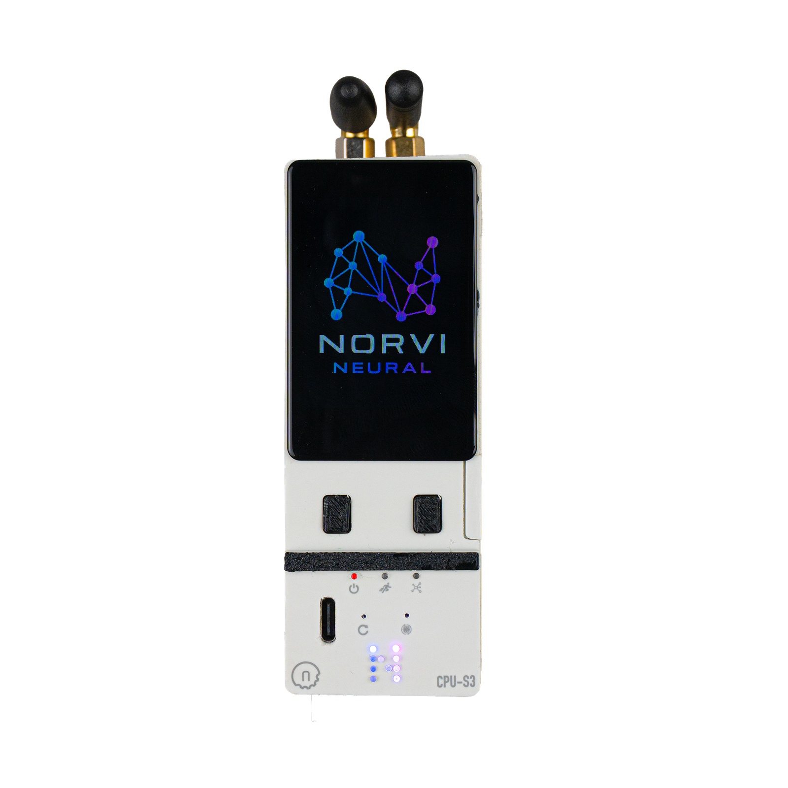
Connect power to the XN. When the device powers up,
you will see the following on the display:
Accessing Neural Deploy #
Neural Deploy is available online and can be accessed using the following link:
Platform:https://deploy.norvi.io/
- No software installation required.
- Accessible through a web browser.
- This applies to NORVI XN devices only
- Neural Deploy updates firmware on your device over the air (OTA), so no USB cable is needed.
Creating an Account #
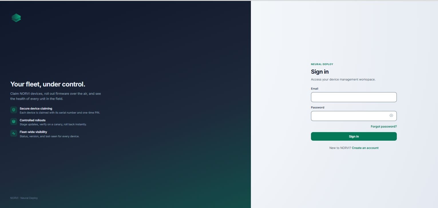
- Open Neural Deploy in a web browser.
- Click the Sign In or Register option on the welcome page.
- Enter the required account details.
- Complete the sign-up process and sign in to Neural Deploy.
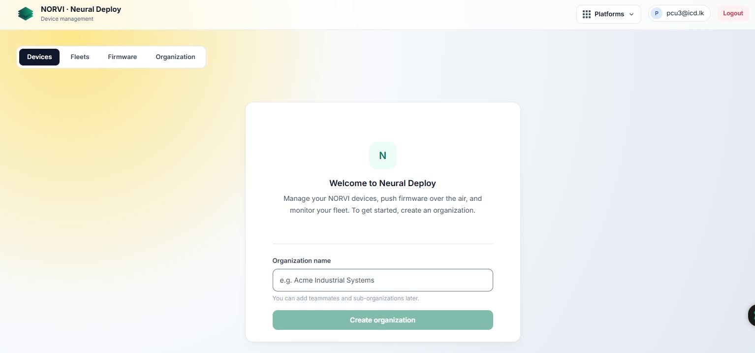
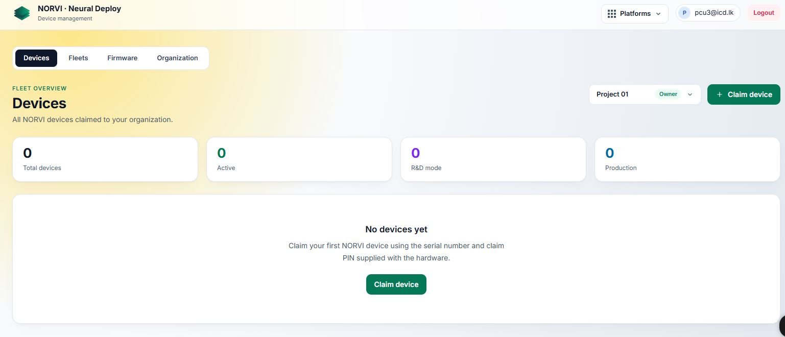
Neural Deploy Dashboard #
The interface shown below opens after you click Neural Deploy. Enter your Organization name.
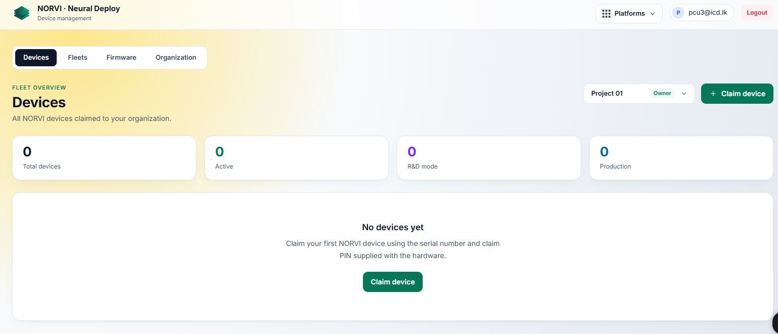
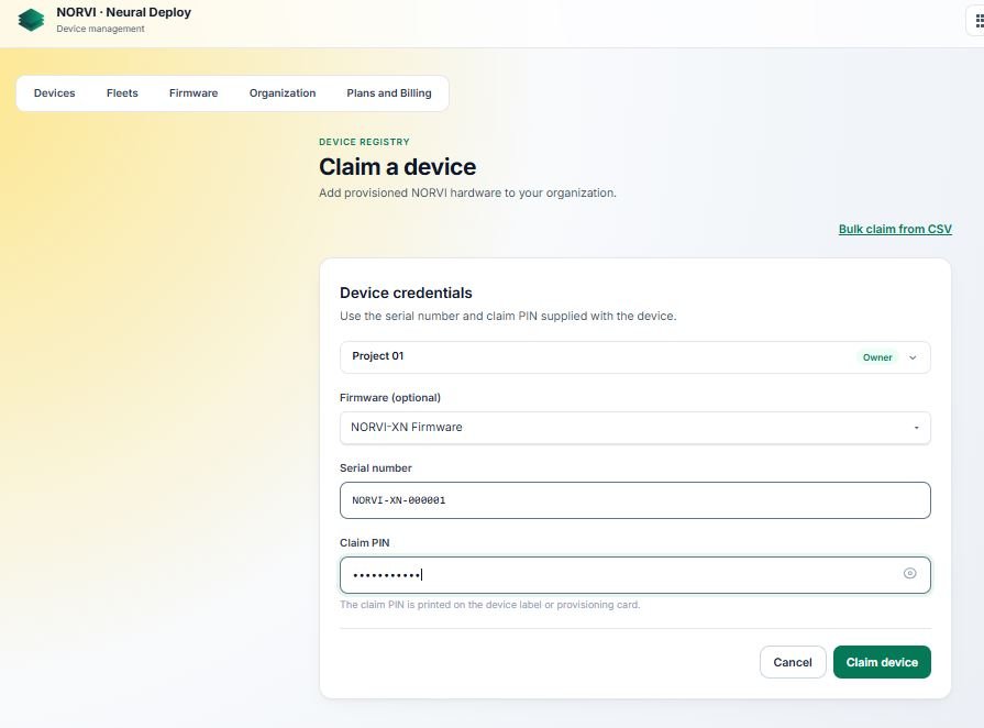
Claim a Device #
Claim your device to your organization by entering the Serial Number and Claim PIN that we provide.
Arduino IDE #
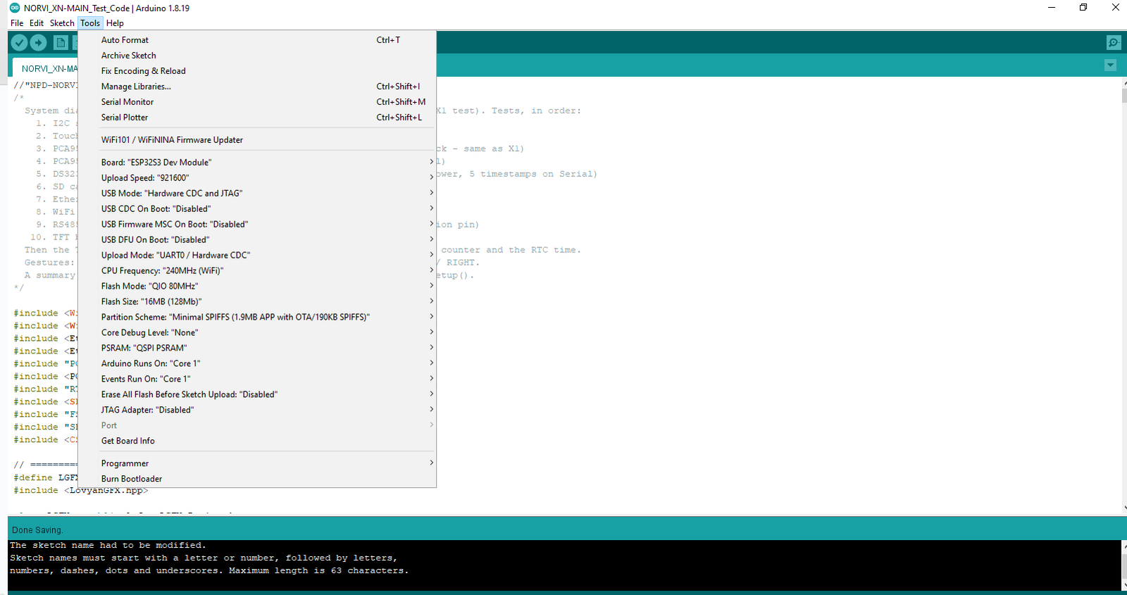
Open Arduino IDE (Arduino IDE is just one option, since you may already be familiar with it. You can also program your device directly in Neural Studio.), select the board settings below for the NORVI XN-MAIN, and write your code. Install the esp32 by Espressif Systems board package and any libraries your code needs before you compile.
- Click Tools.
- Set Board to ESP32S3 Dev Module.
- Set USB CDC On Boot to Disabled.
- Set Flash Size to 16MB (128Mb).
- Set Partition Scheme to Minimal SPIFFS (1.9MB APP with OTA/190KB SPIFFS).
- Set PSRAM to QSPI PSRAM.
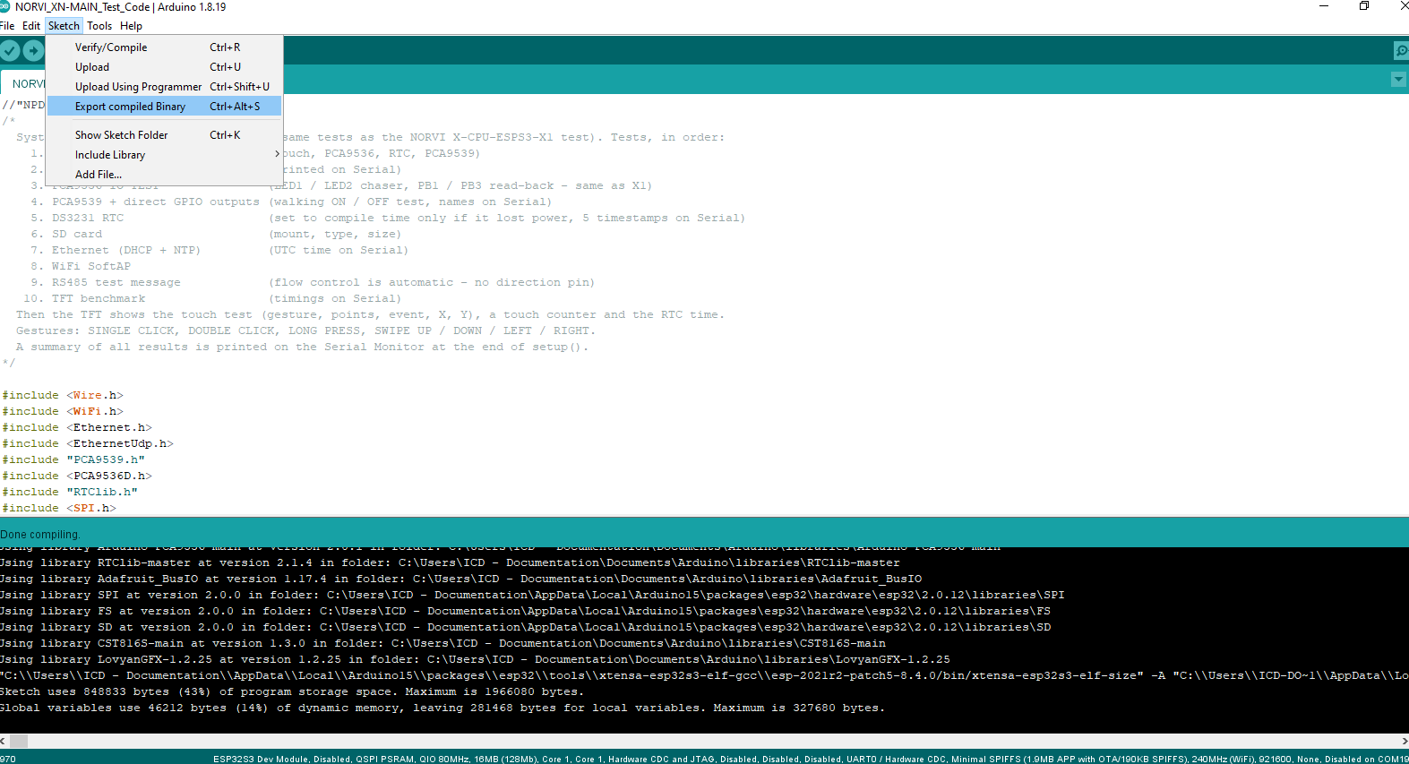
Export Compiled Binary #
Flash a Binary from Arduino IDE with Neural Deploy #
Click Manage to flash a binary exported from Arduino IDE.
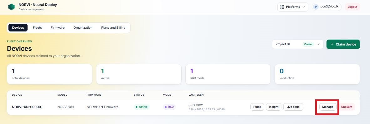
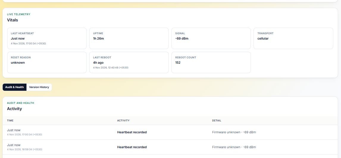
To check whether your device is online, look at the Last Seen field. It displays the last time the device was online or connected.
Creating New Firmware #
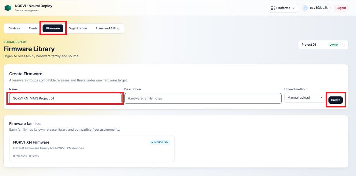
After exporting the binary file, click the Firmware section to create a Firmware Library.
The Firmware interface will appear. To create a new firmware library, enter a name in the provided field and click Create.
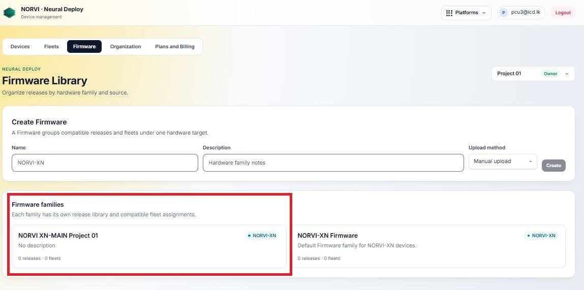
Click on NORVI XN-MAIN Project 01.
Enter the firmware Version and Label, then upload the exported binary file.
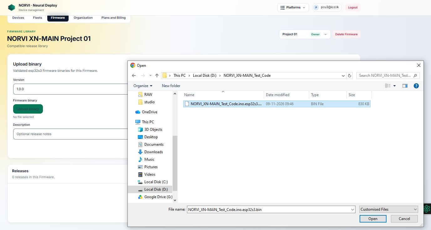
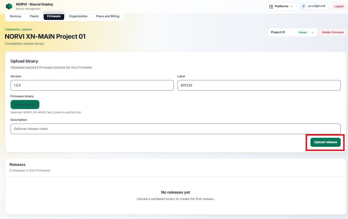
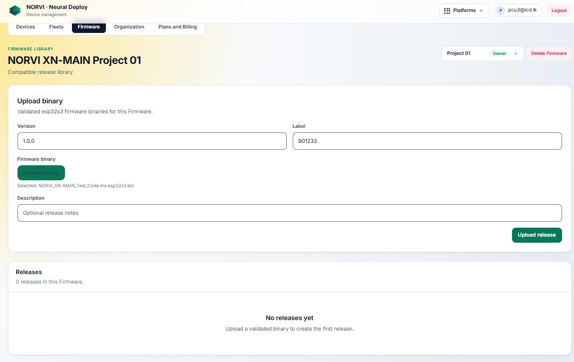
Click Upload to upload the binary file. Once the upload is complete, click Upload Release
Firmware Over-the-Air (FOTA) Management #
Assign the firmware #
Firmware Over-the-Air (FOTA) allows you to upload and update firmware remotely over the air without physically connecting the device to a computer. It also helps manage firmware versions and releases.
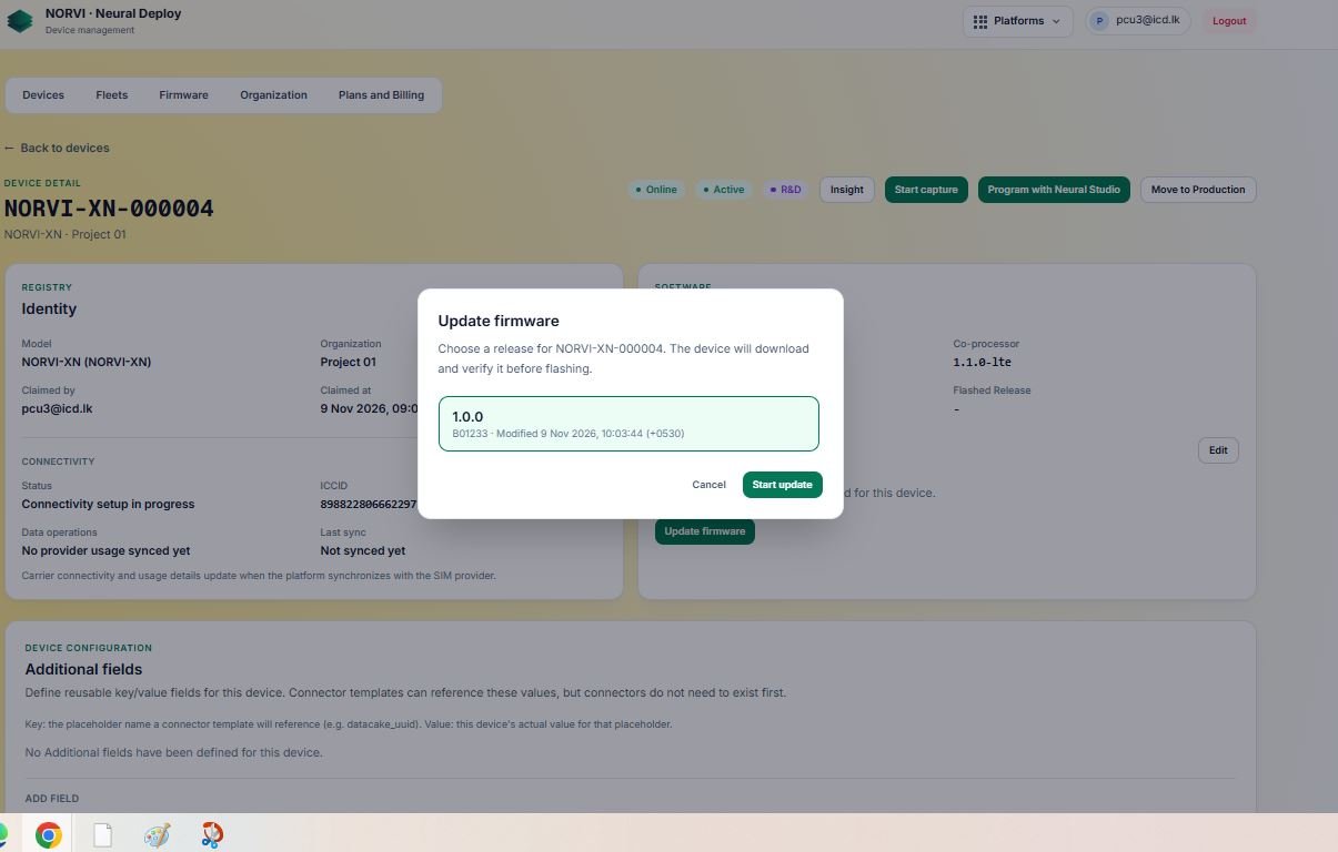
Navigate to Device → Manage → Assign
Assign is also in the Firmware section. Use it to assign the firmware library to your device.
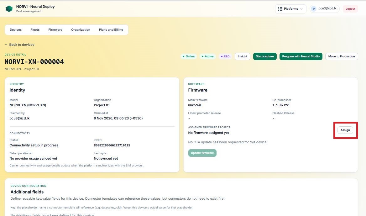
Monitor the firmware update #
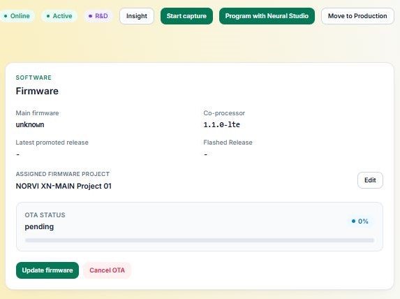
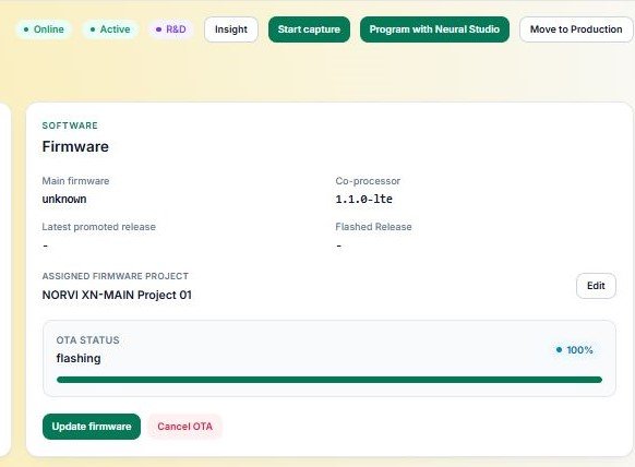
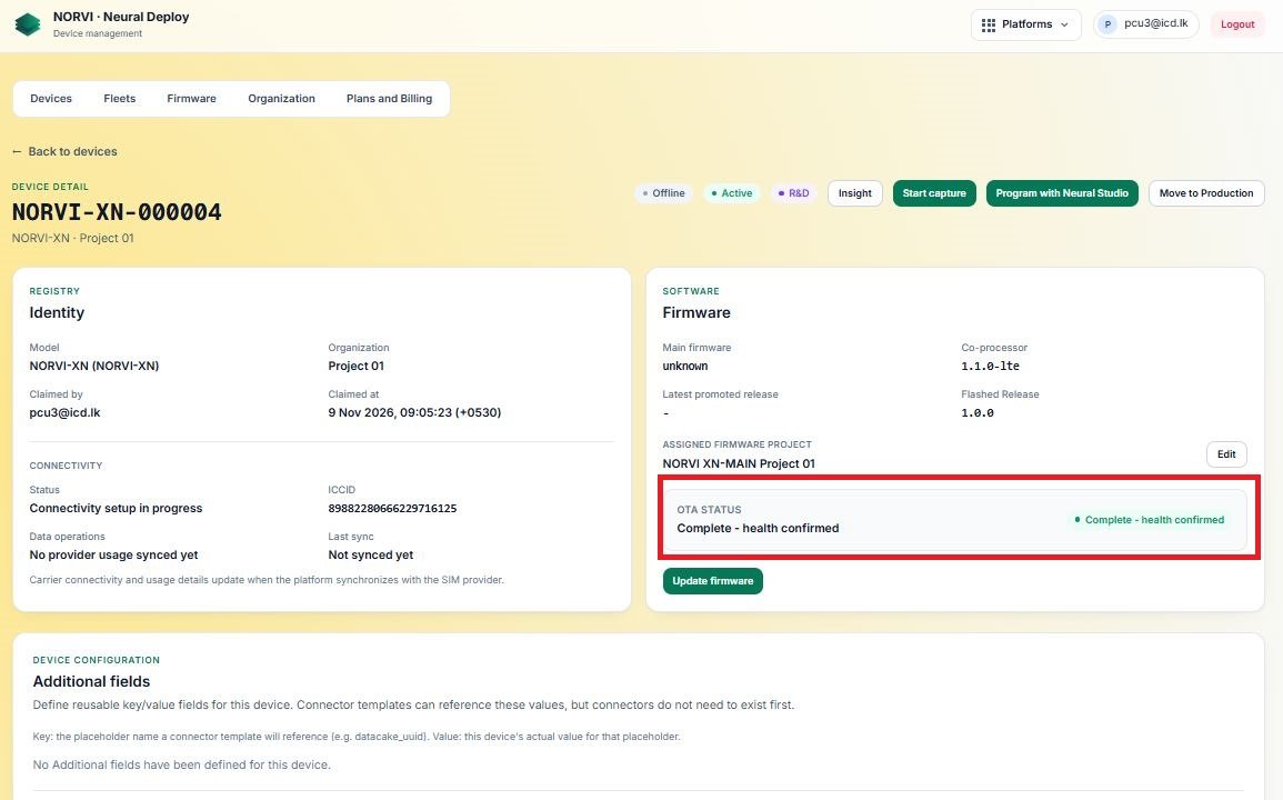
Once the firmware is assigned, the update process will begin with the Pending status. The device will then download the assigned firmware package from the server and verify its integrity. Upon successful verification, the device will proceed with flashing the new firmware.
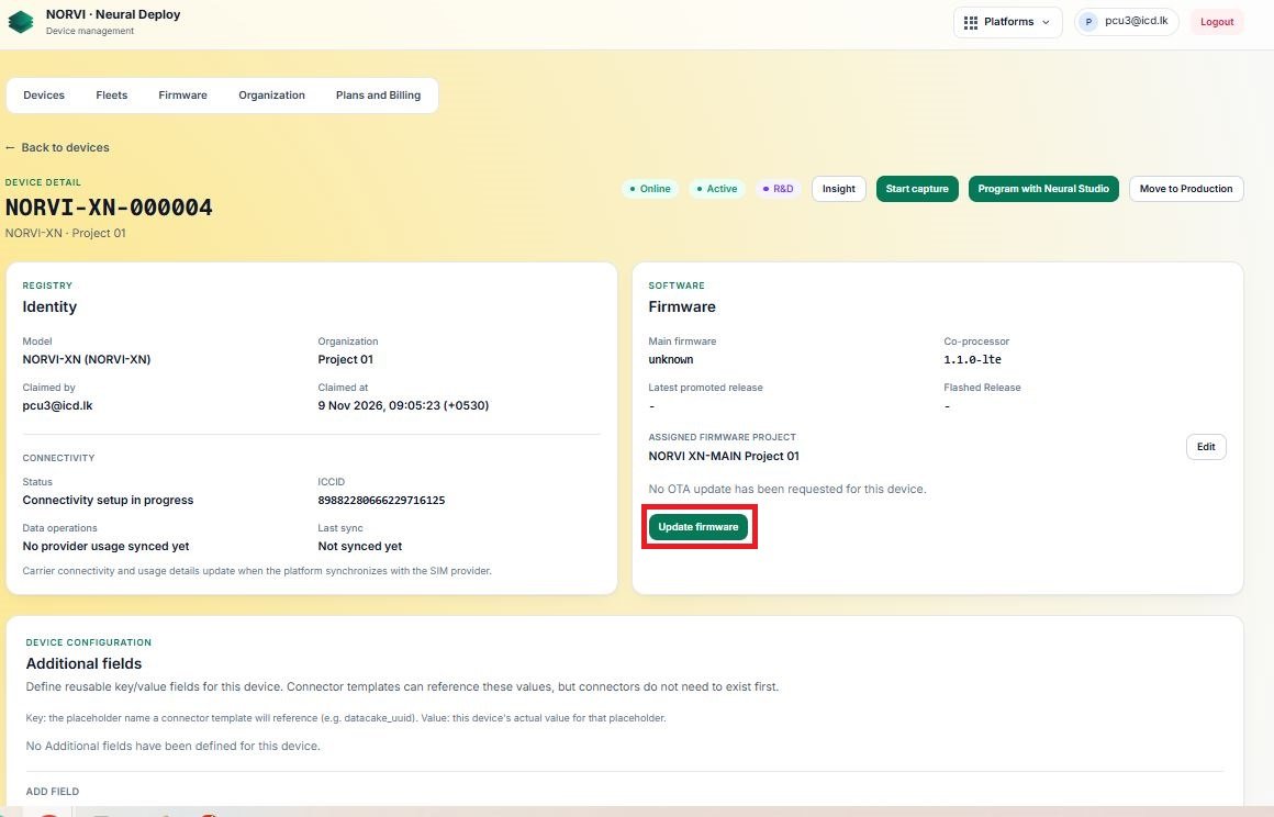
Update the firmware. The device will download the new firmware and verify it before flashing.
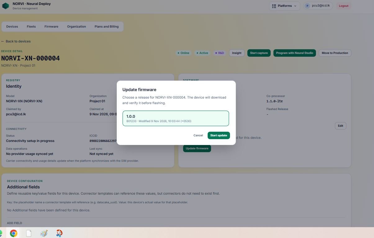
Understand the update statuses #
- Pending: The firmware update has been assigned to the device and is waiting to start.
- Downloading: The device is downloading the new firmware from the server.
- Flashing: The downloaded firmware is being written to the device’s flash memory.
- Upload Successful: The firmware has been successfully uploaded and flashed to the device. The OTA update is complete.
Monitoring Live Serial Output #
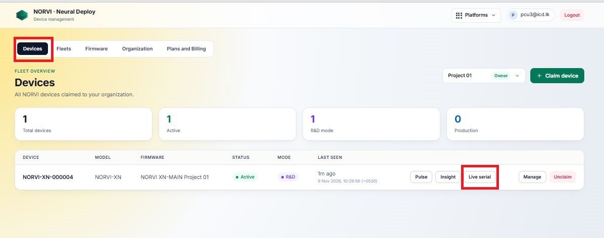
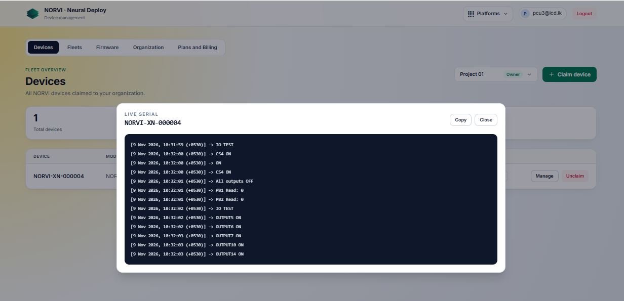
The Live Serial feature provides real-time access to the device’s serial communication, allowing users to monitor application execution and inspect diagnostic messages remotely through Neural Deploy.
The serial output displays messages generated by the application firmware, including status updates, execution logs, and debugging information. This helps identify unexpected behaviour, monitor application processes, and troubleshoot potential firmware issues without requiring a physical USB connection to the device.
Live Serial is particularly useful for:
- Real-Time Monitoring: View serial messages generated by the application while the device is running.
- Debugging: Identify errors, unexpected behaviour, and issues during application execution.
- Application Diagnostics: Track program execution and monitor the device’s operational status.
- Remote Troubleshooting: Inspect serial logs remotely without physically accessing the device.
Verify your device #
After the status shows Complete – health confirmed, open Devices → Live serial to see your sketch’s output in real time.
Troubleshooting #
| Problem | What to check |
|---|---|
| Claim fails | Re-enter the Serial number exactly as printed, and check the Claim PIN on the device label or provisioning card. |
| Device shows Offline | Check that both antennas are attached, the SIM is active, and the 24 V supply is connected. |
| Update stays at Pending | The device has not yet picked up the request. Confirm it is Online, then wait a little while for its next check-in. If the OTA times out, the network connection may be unstable. Wait for some time and try again. |
| Update fails or the old firmware returns | If an OTA update fails, the device rolls back to the previous firmware automatically. Check Live serial for errors, fix the issue, rebuild your binary, and try again. |
| No serial output | Confirm your sketch prints to Serial and that the update reached Complete – health confirmed and also check whether cdc on boot disabled. if cdc on boot enabled serial will not show. |
Additional Resources #
- Official datasheet: NORVI XN-MAIN Datasheet
- Product page: norvi.io/xn