
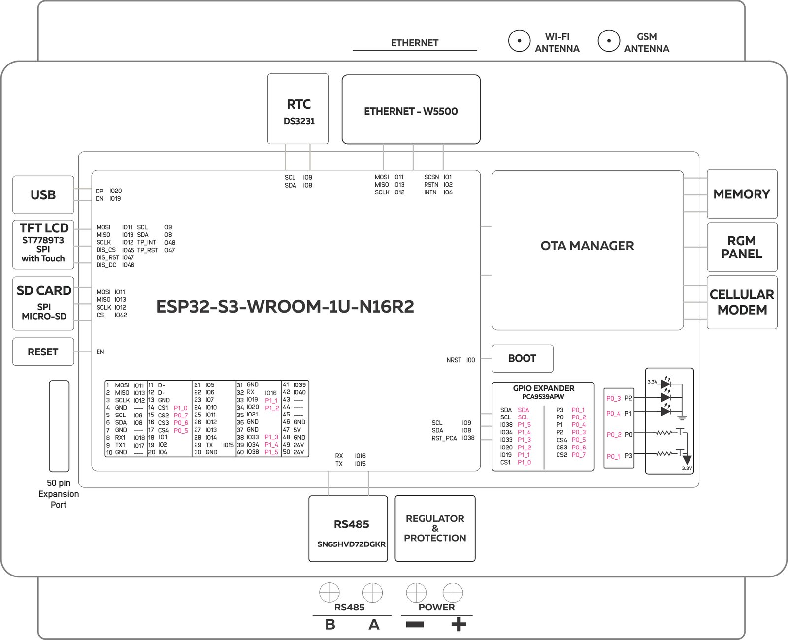
The NORVI XN-MAIN is an industrial controller built around the ESP32-S3-WROOM-1U-N16R2. It combines Ethernet, RS-485, and LTE Cat 1 cellular connectivity with a 2.0″ touch display, real-time clock, and microSD storage. A 50-pin expansion port allows additional NORVI modules to be added, making it suitable for rugged industrial monitoring and control applications.
Product Features #
- ESP32-S3-WROOM-1U-N16R2 Main Controller
- TFT SPI Display with touch input
- Built-in RS-485 Communication
- Built-in Ethernet Communication
- DS3231 Real-Time Clock
- OTA Management
- A7672X LTE Cat 1 Cellular Modem
- USB Programming and Debugging
- DIN-Rail mount
Applications #
- Industrial automation and control systems
- Remote monitoring and telemetry
- IoT gateways and protocol converters
- Modbus RTU to Ethernet or MQTT bridging
- Time-stamped data logging
- Local HMI and operator panels
- Building and energy management systems
- Modular I/O and expansion-based systems
Expansions Supported #
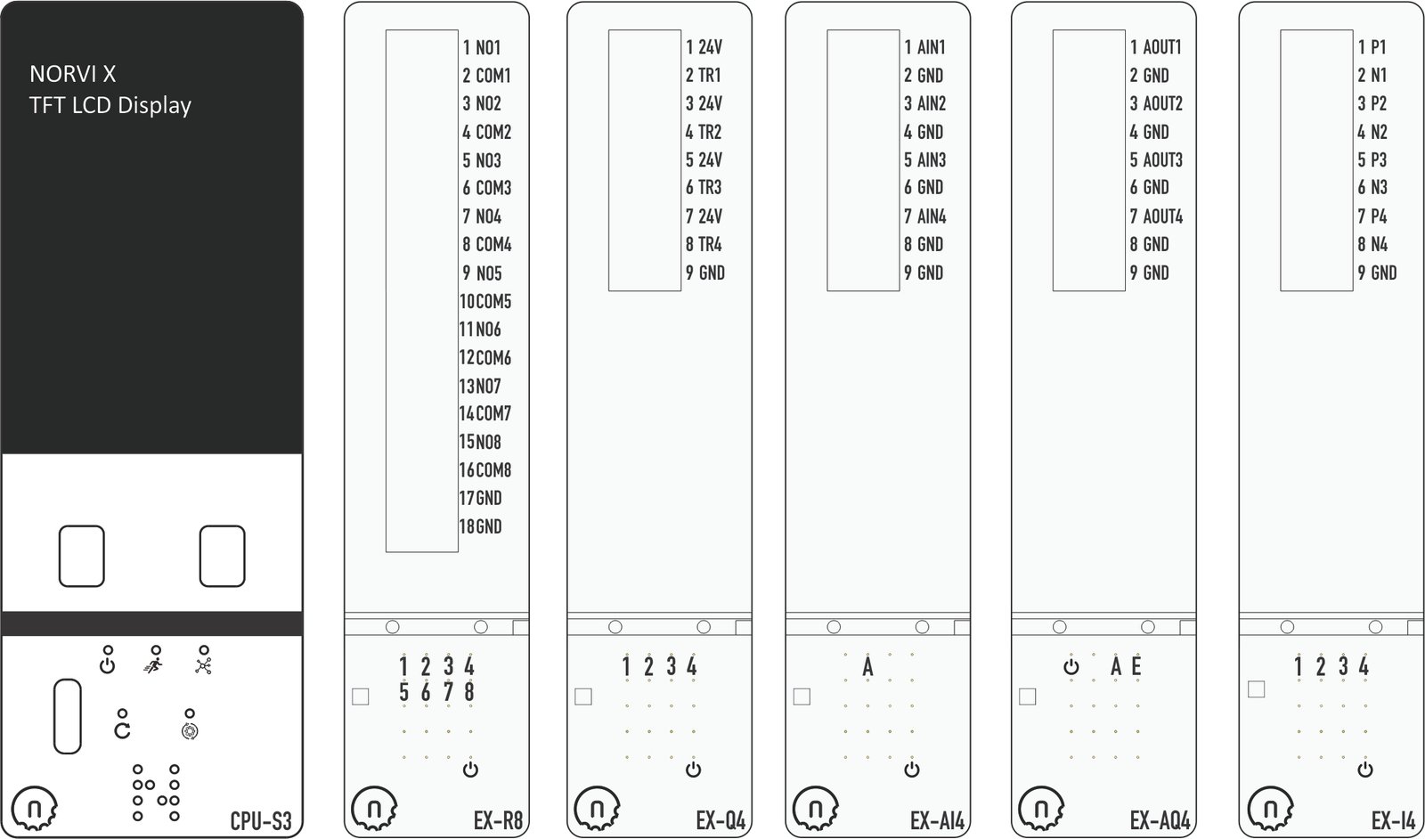
| Digital Input Modules 4 x Digital Inputs 8 x Digital Inputs 16 x Digital Inputs | Relay Output Modules 4 x Relay Output 8 x Relay Output | Transistor Output Modules 4 x Transistor Output 8 x Transistor Output 16 x Transistor Output |
| Analog Input Modules 4 x Analog Inputs 0-10V 4 x Analog Inputs 4-20mA | Analog Output Modules 4 x Analog Outputs 0-10V / 4-20mA | Communication Modules LoraWAN Module RS485, RS232 & UART Module |
| Temperature Input Modules 4 x Temperature Inputs(NTC thermistor(10kΩ ) 4 x Temperature Inputs(PT100 & PT1000) 4 x Temperature Inputs( K-Type Thermocouple) | ||
| Power & Utility Modules 3 x Current Transformer (Energy) | ||
Main #
| Range of Product | NORVI X |
| Product type | Modular Programmable Controller |
| Certifications | EN 61131-2:2007 EN 61010-1:2010+A1:2019 EN IEC 61010-2-201:2018 2014/30/EU- Electromagnetic Compatibility (EMC) Annex III, Part B, Module C |
| Rated supply voltage | 24V DC |
| Communication | WiFI 2.5GHz / Bluetooth Ethernet RS-485 |
| Displays and Visual Indicators | 2.0 inch TFT LCD Display 240*320 |
Complementary #
| Product Unified Code | NORVI XN-MAIN |
| Product Part Numbers | NORVI XN-MAIN |
Mechanical Properties #
| Enclosure | NORVI X |
| Mounting / Installation Method | DIN RAIL |
| Terminal Type | Push-in terminal |
| Terminal Arrangement | Bottom |
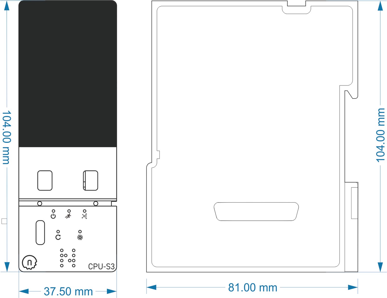
| Length | 81.00 mm |
| Height | 104.00 mm |
| Width | 37.50 mm |
Environment #
| IP degree of protection | IP20 |
| Operating altitude | 0 – 2000 meters |
| Operating Temperature | – –40 … +85° C (-40…185 °F) |
| Storage altitude | 0 – 3000 meters |
| Shock resistance | 15 gn for 11ms |
| Resistance to electrostatic discharge | 4kV on contact 8kV on air |
| Resistance to electromagnetic fields | 10 V/m (80 MHz …… 1GHz) 3 V/m (1.4 MHz …… 2 GHz) 1 V/m (2 MHz …… 3 GHz) |
Electrical Characteristics #
| Rated Supply Voltage (V) | 24V DC |
| Current Consumption (mA) | 90mA – 100mA |
| Maximum Voltage(V) Input | 28V DC |
| Minimum Voltage(V) Input | 9V DC |
| Recommended Power Source | 1A 24V DC |
Grid Powered Devices #
Processing #
| SOC / MCU | ESP32-S3-WROOM-1U-N16R2 |
| Flash Memory | 16MB |
| ROM | 384 KB |
| SRAM | 512 KB |
| PSRAM | 2 MB (Quad-SPI) |
Peripherals #
Micro SD Card Support #
| Card Type | MicroSD |
| Interface | SPI |
| SD CARD CS | IO42 |
| MISO | IO13 |
| MOSI | IO11 |
| SCLK | IO12 |
| SD Detect | NOT CONNECTED |
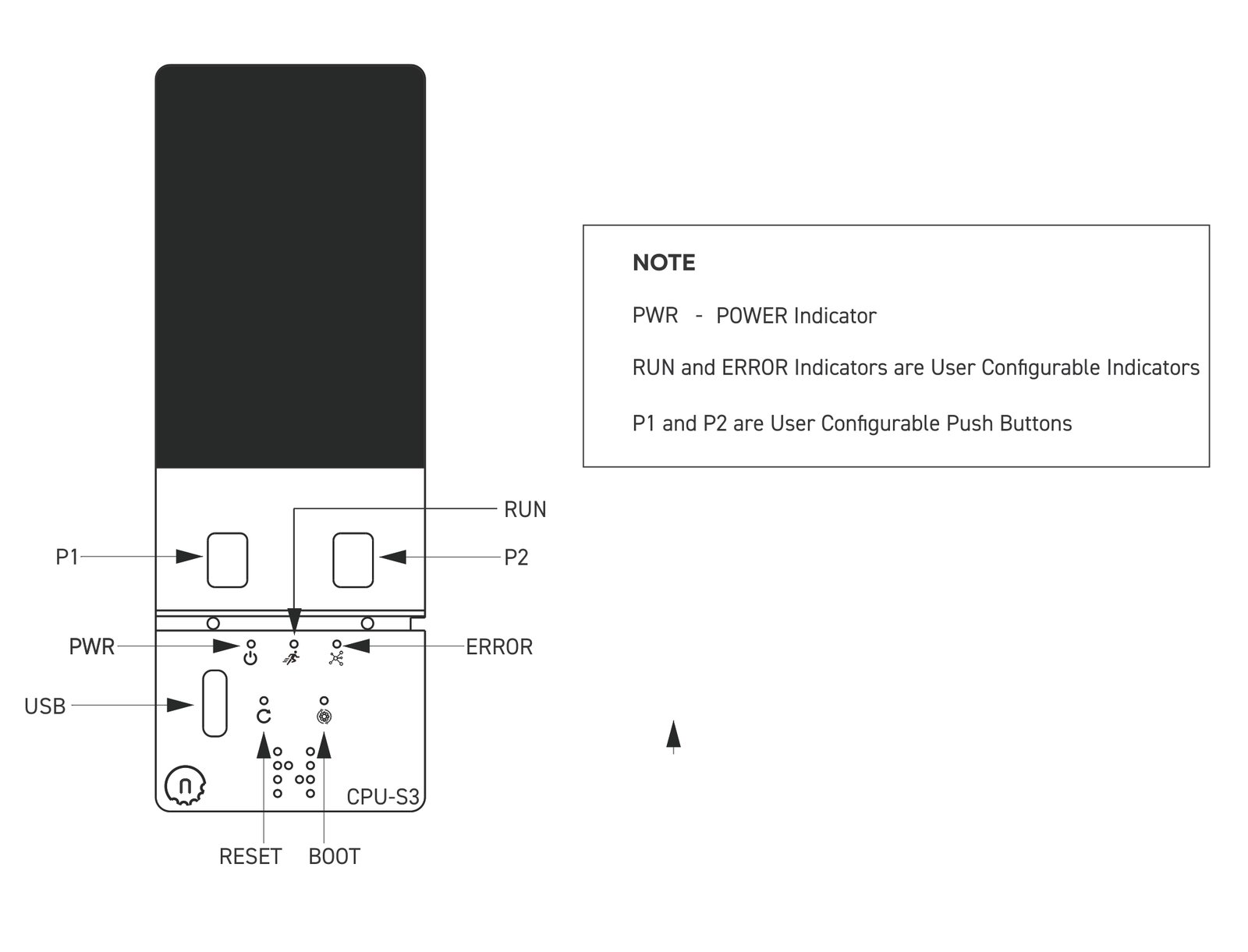
Built-in Buttons #
| Button 1 Pin | P0 | PCA9539APW – P0_2 |
| Button 2 Pin | P3 | PCA9539APW – P0_1 |
Built-in Indicators #
| RUN Indicator | P2 | PCA9539APW – P0_3 |
| ERROR Indicator | P1 | PCA9539APW – P0_4 |
LCD TFT #
| Display Driver | ST7789 |
| Display Size | 2.0 inch |
| MOSI | IO11 |
| MISO | IO13 |
| SCLK | IO12 |
| DIS_CS | IO45 |
| TP RST/ DIS_RST | IO47 |
| DIS_DC | IO46 |
| SCL Pin (Touch Screen) | IO9 |
| SDA Pin (Touch Screen) | IO8 |
| RESET Pin | NOT CONNECTED |
INPUTS and OUTPUTS #
An expansion module from NORVI Controllers should be used to add I/O to the XN-MAIN Module.
Refer products section Link for information on Expansion Modules.
Currently Available Expansion Modules are
| 4 x Digital Inputs |
| 4 x Relay Outputs |
| 4 x Transistor Outputs |
| 4 x Analog Inputs 0-10V |
| 4 x Analog Inputs 4-20mA |
| 4 x Analog Outputs 0-10V / 4-20mA |
| 8 x Digital Inputs |
| 16 x Digital Inputs |
| 8 x Relay Outputs |
| 16 x Transistor Outputs |
| 4 x Thermocouple |
| 4 x Thermistor |
| 8 x Transistor Outputs |
| UART – IO |
| 4 x RTD |
OTA Management #
- Cellular handled by the hardware: The whole network connection is built in. There is no network code to write in your firmware.
- Remote debugging: Watch and troubleshoot the device through a remote serial connection.
- Remote firmware updates: Update the device with no physical access.
- Rollback protection: Restore the previous firmware if an update fails.
- Remote serial logs: View logs remotely for monitoring and troubleshooting.
Communication Channels #
| Communication Mode | HALF-DUPLEX |
| Transceiver | SN65HVD72 |
| Unit Load | 1/4 |
| TX Pin | IO15 |
| RX Pin | IO16 |
| Terminal Arrangement |
A7672X Cellular Communication Specifications #
| Feature | Details |
|---|---|
| Power supply | Power supply VBAT: 3.4V ~4.2V, Recommended VBAT: 3.8V |
| Cellular Standard | LTE Cat 1 |
| LTE-FDD Bands | B1, B3, B5, B8 |
| LTE-TDD Bands | B34, B38, B39, B40, B41 |
| GSM Bands | 900MHz, 1800MHz |
| Protocol Support | TCP/IP/IPV4/IPV6/Multi-PDP/FTP/FTPS/HTTP/HTTPS/DNS/MQTT |
| SMS Support | MT, MO, CB, Text, PDU mode |
GPIO Map #
| GPIO | Utilisation | |
|---|---|---|
| CPU | Expansion Port | |
| 0 | BOOT Button | NC |
| 1 | SCSN – Ethernet | IO1 |
| 2 | RSTN – Ethernet | IO2 |
| 3 | – | – |
| 4 | INTN – Ethernet | IO4 |
| 5 | IO5 | |
| 6 | IO6 | |
| 7 | IO7 | |
| 8 | SDA | SDA |
| 9 | SCL | SCL |
| 10 | IO10 | |
| 11 | MOSI | MOSI |
| 12 | SCLK | SCLK |
| 13 | MISO | MISO |
| 14 | IO14 | |
| 15 | RS485 – TX | IO15 |
| 16 | RS485 – RX | IO16 |
| 17 | TX1 | |
| 18 | RX1 | |
| 19 | USB – DN | D_N |
| 20 | USB – DP | D_P |
| 21 | IO21 | |
| 35 | IO11 | |
| 36 | IO36 | |
| 37 | IO13 | |
| 38 | PCA9536 – RESET | RST_PCA |
| 39 | IO39 | |
| 40 | IO40 | |
| 41 | IO12 | |
| 42 | SD CARD – CS | NC |
| 45 | CS – TFT DISPLAY | NC |
| 46 | DC – TFT DISPLAY | NC |
| 47 | RESET – TFT DISPLAY | NC |
| 48 | INTERRUPT – TOUCH PANEL | NC |
Expansion Port #
| PIN INDEX | Purpose | GPIO | SOURCE |
|---|---|---|---|
| 1 | MOSI | IO11 | ESP32-S3 |
| 2 | MISO | IO13 | |
| 3 | SCLK | IO12 | |
| 4 | GND | —- | |
| 5 | SCL | IO9 | |
| 6 | SDA | IO8 | |
| 7 | GND | —- | |
| 8 | RX1 | IO18 | |
| 9 | TX1 | IO17 | |
| 10 | GND | —- | |
| 11 | D+ | IO20 | |
| 12 | D- | IO19 | |
| 13 | GND | —- | |
| 14 | CS1 | P1_0 | PCA9539 I2C Address 0x75 |
| 15 | CS2 | P0_7 | |
| 16 | CS3 | P0_6 | |
| 17 | CS4 | P0_5 | |
| 18 | IO1 | IO1 | ESP32-S3 |
| 19 | IO2 | IO2 | |
| 20 | IO4 | IO4 | |
| 21 | IO5 | IO5 | |
| 22 | IO6 | IO6 | |
| 23 | IO7 | IO7 | |
| 24 | IO10 | IO10 | |
| 25 | IO11 | IO35 | |
| 26 | IO12 | IO41 | |
| 27 | IO13 | IO37 | |
| 28 | IO14 | IO14 | |
| 29 | RS485_TX | IO15 | |
| 30 | GND | —- | |
| 31 | GND | —- | |
| 32 | RS485_RX | IO16 | |
| 33 | P1_1 | P1_1 | PCA9539 I2C Address 0x75 |
| 34 | P1_2 | P1_2 | |
| 35 | IO21 | IO21 | ESP32-S3 |
| 36 | GND | —- | |
| 37 | GND | —- | |
| 38 | P1_3 | P1_3 | PCA9539 I2C Address 0x75 |
| 39 | P1_4 | P1_4 | |
| 40 | P1_5 | P1_5 | |
| 41 | IO39 | IO39 | ESP32-S3 |
| 42 | IO40 | IO40 | |
| 43 | IO36 | IO36 | |
| 44 | NC | —- | |
| 45 | NC | —- | |
| 46 | GND | —- | |
| 47 | 5V | 5V | |
| 48 | GND | GND | |
| 49 | 24V | 24V | |
| 50 | 24V | 24V |
| Product Type | MCU / PSRAM | Expansion Compatibility | Notes |
|---|---|---|---|
| Standard Product | ESP32-S3 (N16R2) – PSRAM via QSPI | All expansion modules supported | – |
| Customized Product | ESP32-S3 (N16R8) – PSRAM via OPI | All except X-Q4 expansion | X-Q4 not supported on this variant |
REVISION HISTORY #
| Rev. | Date | Change Description | Board Revision |
|---|---|---|---|
| 1.0 | 23/10/2026 | Initial release | V4 |