
Overview #
NORVI X is a next generation modular industrial controller designed to power smart automation and IoT solutions. Built around a CPU module and a range of plug and play expansion modules, the platform scales from a handful of I/O points up to 200, giving system integrators, OEMs, and industrial engineers a flexible foundation for automation, remote monitoring, and data acquisition projects.
The NORVI X-T4 is a 4 channel thermistor input expansion module built for this platform. It provides four analog input channels dedicated to NTC (Negative Temperature Coefficient) thermistor(10kΩ) -based temperature sensing. Each channel is read through a shared 16-bit ADS1115 I2C ADC, which keeps the module simple to add without using up extra MCU pins on the CPU module beyond the shared I2C bus. The X-T4 is not a standalone device. It needs to be paired with a NORVI X CPU module, such as the CPU ESPS3 X1, to be programmed and operated.
This guide covers everything needed to confidently install, wire, and commission the module, including safety requirements, technical specifications, terminal and address configuration, wiring steps, software setup, diagnostic test code, and troubleshooting.
Key Features #
- 4 analog input channels for NTC thermistor(10kΩ)-based temperature sensing
- Each channel read through a shared 16-bit ADS1115 I2C ADC for high-resolution measurement
- I2C communication interface, so only two GPIOs (SCL and SDA) are used from the CPU
- Suitable for multi-zone industrial temperature monitoring
- Onboard DIP switch for I2C address selection, allowing multiple thermistor modules on the same bus
- DIN rail mountable enclosure with spring terminals
- Plug and play connection to the CPU module through the expansion bus
- CE / EMC compliant (EN 61131-2:2007, EN 61010-1:2010+A1:2019, EN IEC 61010-2-201:2018, 2014/30/EU)
Safety Information #
Warning: Disconnect all power sources before installing, wiring, or servicing the NORVI X-T4. Failure to do so may result in electric shock or damage to the equipment.
- Install and wire this module only if you are a qualified electrician or trained technician familiar with industrial control equipment.
- Confirm the host CPU is running from a regulated 24 V DC supply, since the module draws its power through the expansion port rather than a separate connection.
- This module reads low-level analog signals from thermistors to keep sensor wiring running short and separated from AC power or relay wiring to avoid measurement noise and error.
- Mount the module on a DIN rail inside a suitably rated enclosure. It carries an IP20 protection rating and is not designed for direct outdoor or wash down exposure.
- Keep the operating environment within minus 40 to plus 85 degrees C and avoid condensing humidity.
- Do not connect or disconnect the module from the expansion bus while the system is powered.
- Follow all local and national electrical codes applicable to industrial control panel wiring.
Technical Specifications #
Electrical #
| Rated Supply Voltage | 24V DC |
| Current Consumption | 40mA @ 24V DC |
Input Specifications #
| Number of Thermistor Inputs | 4 |
| Analog to Digital Converter (ADC) | ADS1115, 16-bit, I2C, 3.3V supply |
| Thermistor Type | NTC (Negative Temperature Coefficient) / (10kΩ) |
| B-Value | Approx. 3950 K |
| Resistance / B-Value Tolerance | ±1% to ±3% |
| Sensor Configuration | 2-wire NTC thermistor |
| Sensor Operating Temperature Range | At least -40°C to +125°C |
| Output Diagnostics | Alert Indicator |
| Power supply | 24V DC, shared with CPU through the expansion port |
| Communication bus | Internal expansion bus (I2C) |
| Connector Type | Spring terminal |
Hardware Layout & GPIO Map #
The table below lists the terminals on the X-T4 and how they map into the ADS1115 ADC. Unlike relay or digital I/O modules, none of the host CPU’s GPIO pins are claimed by the sensor channels themselves – only SCL and SDA are shared across the I2C bus.
| Terminal | Function |
| TM1+ | Positive Input – Channel 1 |
| TM1- | Negative Input – Channel 1 |
| TM2+ | Positive Input – Channel 2 |
| TM2- | Negative Input – Channel 2 |
| TM3+ | Positive Input – Channel 3 |
| TM3- | Negative Input – Channel 3 |
| TM4+ | Positive Input – Channel 4 |
| TM4- | Negative Input – Channel 4 |
| AGND | Analog Ground |
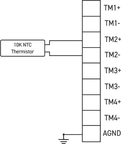
Each channel is a 2-wire NTC thermistor input. To read a channel, connect the thermistor’s two leads across the TM_n+ and TM_n- terminals for that channel; AGND provides the shared analog reference for the module.
I2C Address Selection
| Address Selection | ||||
| DIP 1 | DIP 2 | DIP 3 | DIP 4 | Address |
| ON | OFF | OFF | OFF | 0x49 |
| OFF | ON | OFF | OFF | 0x4B |
| OFF | OFF | ON | OFF | 0x4A |
| OFF | OFF | OFF | ON | 0x48 |
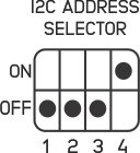
Note: the ADS1115 that directly drives the 4 thermistor input channels is itself addressed at 0x48; the DIP-selectable addresses apply when the module is daisy-chained with other I2C-addressed NORVI expansion modules on the same bus.
Wiring Guide #
GPIO pin assignments for the I2C bus are listed in the Expansion Port table below (Section 6.4); this section covers how to physically wire the module, not the pin numbers themselves.
Power Connection #
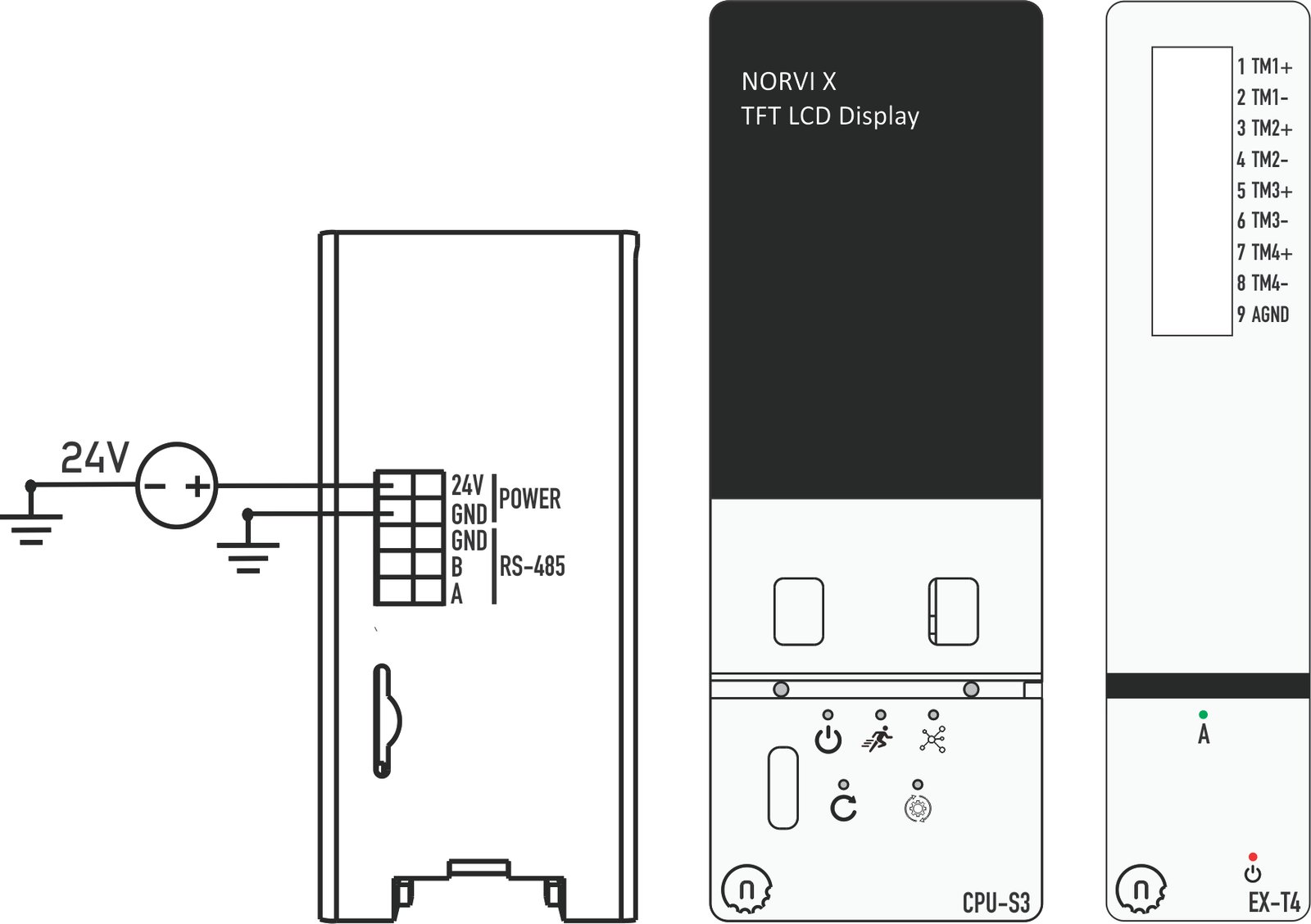
The X-T4 requires no separate power supply. It receives 24V DC from the CPU module through the shared expansion port connector, provided the CPU is powered from a regulated 24V DC source with adequate current headroom.
Thermistor Input Wiring #
- Each of the four channels is a 2-wire NTC thermistor input.
- Connect the two leads of each thermistor across the TM_n+ and TM_n- terminals for that channel.
- AGND provides the shared analog ground reference for all four channels.
- Keep thermistor wiring runs short, and route them separately from AC power, relay, or motor wiring to minimize induced noise on the analog signal.
- If extending the sensor leads over long distances, use shielded twisted-pair cable and ground the shield at one end only.
- Confirm each thermistor’s resistance at a known temperature (e.g. room temperature) with a multimeter before wiring, to catch a faulty sensor early.
Mounting and Connecting the Module #
- Power off the entire system before touching any wiring or seating the module.
- Mount the X-T4 on the DIN rail next to the CPU module (or next to another expansion module already in the chain) and seat it firmly onto the expansion bus connector.
- Set the I2C address using the onboard DIP switches. Leave at the default for a single X-T4; if adding more than one I2C-addressed module to the same bus, set a unique address on each. See the I2C Address Selection table in Section 5.1.
- Wire your thermistors to the TM1 through TM4 terminal pairs, connecting each sensor’s two leads to the + and – terminals for that channel, with AGND as the shared reference.
- Power the system back on.
- Upload the module’s test sketch from the NORVI GitHub repository to confirm each channel reads correctly before wiring it into your final control logic.
Expansion Port (50 pin) #
The X-T4 connects to the CPU through the shared 50-pin expansion bus. The pins actually used by this module are SCL, SDA, GND, 5V, and 24V. The rest pass through for other modules on the same bus.
| PIN INDEX | Purpose | GPIO | SOURCE |
|---|---|---|---|
| 1 | MOSI | IO11 | ESP32-S3 |
| 2 | MISO | IO13 | |
| 3 | SCLK | IO12 | |
| 4 | GND | —- | |
| 5 | SCL | IO9 | |
| 6 | SDA | IO8 | |
| 7 | GND | —- | |
| 8 | RX1 | IO18 | |
| 9 | TX1 | IO17 | |
| 10 | GND | —- | |
| 11 | D+ | —- | |
| 12 | D- | —- | |
| 13 | GND | —- | |
| 14 | CS1 | P1_0 | PCA9539 I2C Address 0x75 |
| 15 | CS2 | P0_7 | |
| 16 | CS3 | P0_6 | |
| 17 | CS4 | P0_5 | |
| 18 | IO1 | IO1 | ESP32-S3 |
| 19 | IO2 | IO2 | |
| 20 | IO4 | IO4 | |
| 21 | IO5 | IO5 | |
| 22 | IO6 | IO6 | |
| 23 | IO7 | IO7 | |
| 24 | IO10 | IO10 | |
| 25 | IO11 | IO35 | |
| 26 | IO12 | IO41 | |
| 27 | IO13 | IO37 | |
| 28 | IO14 | IO14 | |
| 29 | RS485_TX | IO15 | |
| 30 | GND | —- | |
| 31 | GND | —- | |
| 32 | RS485_RX | IO16 | |
| 33 | P1_1 | P1_1 | PCA9539 I2C Address 0x75 |
| 34 | P1_2 | P1_2 | |
| 35 | IO21 | IO21 | ESP32-S3 |
| 36 | GND | —- | |
| 37 | GND | —- | |
| 38 | P1_3 | P1_3 | PCA9539 I2C Address 0x75 |
| 39 | P1_4 | P1_4 | |
| 40 | P1_5 | P1_5 | |
| 41 | IO39 | IO39 | ESP32-S3 |
| 42 | IO40 | IO40 | |
| 43 | NC | —- | |
| 44 | NC | —- | |
| 45 | NC | —- | |
| 46 | GND | —- | |
| 47 | 5V | 5V | |
| 48 | GND | GND | |
| 49 | 24V | 24V | |
| 50 | 24V | 24V |
Software Setup (Arduino IDE) #
The NORVI X-T4 is read through the host CPU using the Arduino IDE with the ESP32 board package. Firmware examples and required libraries are maintained in the NORVI GitHub repository.
Board Configuration #
- Install Arduino IDE
Install the Arduino IDE and add ESP32 board support:
Tools → Board → Boards Manager → ESP32
- Connect the Controller
Connect the NORVI X CPU to your computer using the USB interface.
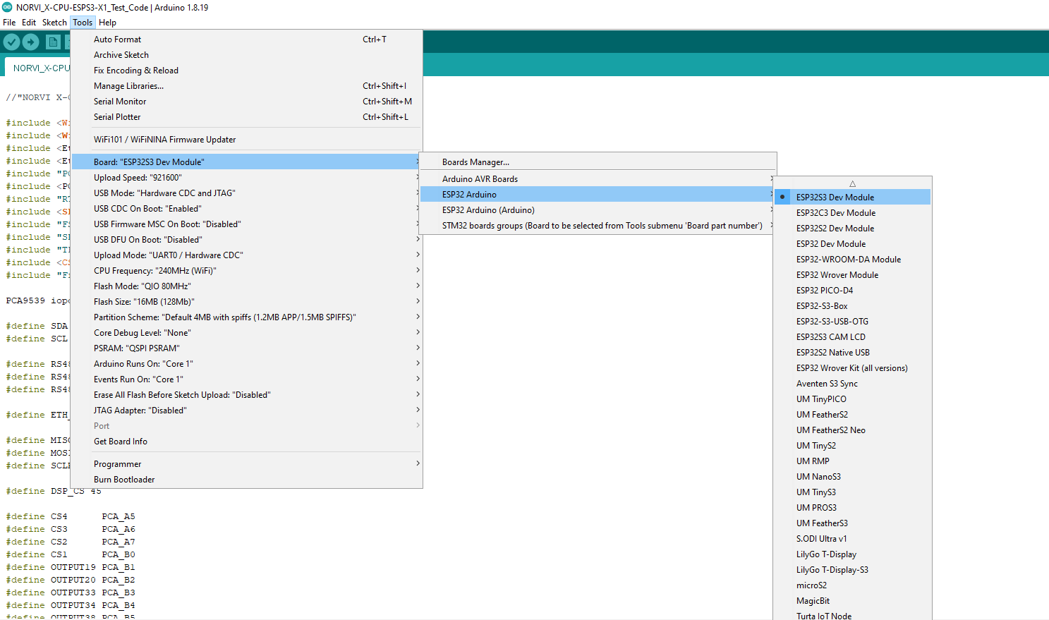
- Select Board and Port
Configure the board and communication port:
- Tools → Board → ESP32 Arduino → ESP32S3 Dev Module
- Tools → Port → Select the corresponding COM/serial port
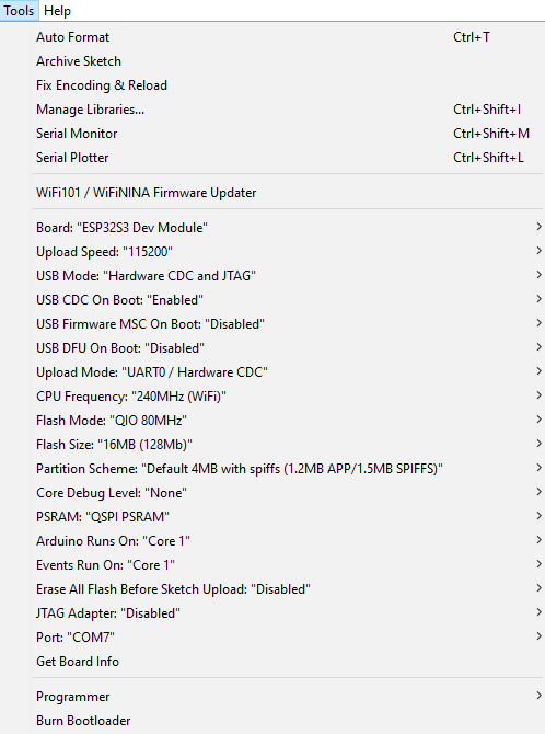
- Configure Board Settings
Under the Tools menu, configure the following settings:
| Setting | Selection |
| USB CDC On Boot | Enabled |
| Flash Size | 16MB (128Mb) |
| PSRAM | QSPI PSRAM |
Test Code Examples #
Required Libraries #
Install these via Arduino IDE → Sketch → Include Library → Manage Libraries before compiling any of the examples below:
- Wire
- WiFi
- SPI
- Adafruit_ADS1X15
- TFT_eSPI
- Free_Fonts
Install the Required Library #
Install the Wire library through:
Sketch → Include Library → Manage Libraries
Search for Wire and install it if required.
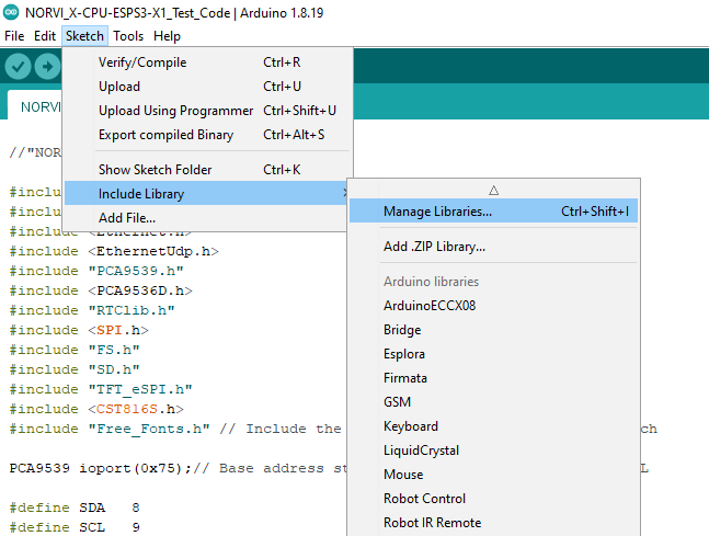
The Libraries are available in the NORVI-X-Version-02 GitHub repository.
Open and Upload the Test Sketch #
- Open the X-T4 test sketch from the NORVI GitHub repository.
- Verify the board and port selections.
- Click Upload to upload the test sketch to the NORVI X CPU.
I2C Bus Scan #
Run this first after wiring and setting the DIP switch address, to confirm the ADS1115 on the X-T4 is being detected before testing thermistor readings.
// I2C SCANNER
void I2C_SCAN() {

  byte error;
  byte address;

  int deviceCount = 0;

  Serial.println();
  Serial.println("Scanning...");

  for (address = 1; address < 127; address++) {

    Wire.beginTransmission(address);

    error = Wire.endTransmission();

    if (error == 0) {

      Serial.print("I2C device found at address 0x");

      if (address < 16) {
        Serial.print("0");
      }

      Serial.print(address, HEX);

      Serial.println(" !");

      deviceCount++;

      delay(1);
    }

    else if (error == 4) {

      Serial.print("Unknown error at address 0x");

      if (address < 16) {
        Serial.print("0");
      }

      Serial.println(address, HEX);
    }
  }

  if (deviceCount == 0) {

    Serial.println("No I2C devices found");

  }
  else {

    Serial.println("Scanning complete");

  }
}
Thermistor Channel Read #
A simple sequence that reads all four raw ADC channels on the ADS1115, useful for confirming each physical terminal responds before applying the temperature conversion.
int16_t adc0;
int16_t adc1;
int16_t adc2;
int16_t adc3;

adc0 = ads1.readADC_SingleEnded(0);
adc1 = ads1.readADC_SingleEnded(1);
adc2 = ads1.readADC_SingleEnded(2);
adc3 = ads1.readADC_SingleEnded(3);

}
Converting Readings to Temperature #
The Beta equation below converts a channel’s resistance to temperature. It assumes a fixed series (bias) resistor forms a voltage divider with the thermistor, which the ADS1115 then reads.
float temp0 = readThermistorC(adc0);
float temp1 = readThermistorC(adc1);
float temp2 = readThermistorC(adc2);
float temp3 = readThermistorC(adc3);
Validating the Full Test Sketch #
When the complete test sketch runs successfully with the X-T4 attached, you should see:
- I2C scans the ADS1115 on the X-T4 appears at its configured address (0x48-0x4B depending on DIP setting) alongside any other I2C devices on the bus.
- Channel readings all four channels return stable, non-zero raw values that change when a thermistor is warmed, cooled, or disconnected.
- Temperature output – once the series resistor and scaling are confirmed, converted values track ambient/applied temperature sensibly (e.g. near room temperature at idle).
- No I2C errors – the Serial Monitor shows no failed transmissions or address conflicts while the test runs.
If a channel does not respond, or the ADS1115 does not appear on the I2C scan, stop and check the wiring and DIP switch address before relying on any readings.
Troubleshooting #
| Symptom | Suggested Action |
| Module not detected on I2C scan | Reseat the module on the expansion bus, confirm the DIP switch address does not conflict with another module, and check the CPU is powered with sufficient current headroom. |
| Reads negative or erratic temperature | Check thermistor wiring polarity and connections at TM_n+ / TM_n- / AGND, and confirm the sensor itself with a multimeter. |
| All channels read the same or a stuck value | Confirm the ADS1115 I2C address in your sketch matches the DIP switch setting, and rerun the I2C bus scan. |
| Address conflict with another I2C module | Change the DIP switch setting on one of the modules so each device on the bus has a unique address. |
| Readings noisy or unstable | Separate thermistor wiring from AC power or relay wiring runs; consider shielded cable for longer sensor leads. |
| Temperature values plausible but offset from actual | Confirm the series resistor value and R25/B-value constants used in the conversion match the actual sensor and module design. |
| System resets unexpectedly under load | Check the CPU’s power supply current rating, especially when several expansion modules are attached to the same bus. |