Pulse-output water meters
Remote totalization for distribution meters, submeters, reservoirs, pump stations and isolated utility assets.

Turn an existing meter's pulse output into remotely accessible consumption data. The NORVI EC-M12-BC-C6-C-C combines two configurable digital inputs, local microSD storage and low-power cellular telemetry in an IP67 battery-powered field node.
Many water, gas and energy meters expose a pulse output proportional to measured consumption. Instead of replacing that meter, the pulse can be counted at the edge, converted using the meter's pulse value, stored locally and sent to a remote platform at the interval your application needs. For remote sites without convenient mains power, explore the full battery-powered cellular IoT data logger platform.
Connect a compatible pulse output to one of the EC-M12 Model C digital inputs.
Firmware increments a pulse counter and can preserve cumulative values between communication cycles.
Translate pulse counts into consumption or interval flow using the meter manufacturer's documented pulse relationship.
Send totals, interval usage, battery status and other application data through LTE-M, NB-IoT or 2G where supported.
Use the same telemetry pattern wherever a field meter exposes a compatible electrical pulse proportional to consumption, flow, volume or energy.
Remote totalization for distribution meters, submeters, reservoirs, pump stations and isolated utility assets.
Collect periodic consumption totals from compatible gas meters where manual readings are slow or expensive.
Capture electrical energy pulses for remote submetering workflows after verifying the meter's pulse interface requirements.
Track distributed irrigation flow and total water use from off-grid or difficult-to-reach field locations.
Bring pulse totals from tenant, process or facility submeters into a central monitoring application.
Use pulse totalization for compatible industrial flow meters when periodic remote consumption data is the main requirement.
“Pulse output” describes a measurement method, not one universal electrical interface. Confirm the meter's output circuit, signal level, pulse width and expected pulse rate before final deployment.
| Meter output | What to verify | EC-M12 integration guidance | Status |
|---|---|---|---|
| Active voltage pulse | 3.3V, 5V or 12V level, pulse width, polarity and common reference. | Strong direct-fit candidate when the meter output matches the documented selectable digital-input level. | Best documented fit |
| Open collector / NPN | Required pull-up voltage, sink current, polarity and wiring reference. | May need a pull-up or interface arrangement depending on the meter's output circuit. Verify before connection. | Verify circuit |
| Dry contact / reed switch | Wetting voltage/current, contact bounce, maximum pulse rate and cable length. | Typically requires a suitable pull-up/input arrangement and debounce strategy in hardware or firmware. | Verify circuit |
| S0 energy-meter pulse | S0 voltage/current specification, isolation requirement, pulse width and local regulations. | Do not assume direct connection. Use the meter documentation to determine whether an interface or isolator is required. | Interface may be needed |
The public EC-M12-BC-C6-C-C datasheet documents two digital inputs and selectable 3.3V / 5V / 12V input levels, but it does not publish a maximum pulse frequency. Confirm the meter's maximum pulse rate and minimum pulse width with NORVI before specifying the logger for high-frequency counting.
The exact conversion comes from the meter manufacturer. Store the pulse relationship as a configurable parameter so the same firmware can support different meter sizes and pulse values.
Example: 1 pulse = 10 litres. A count of 1,250 pulses represents 12,500 litres.
Example: K = 100 pulses/m³. A count of 2,500 pulses represents 25 m³.
Choose around the meter signal, available power, network coverage, pulse frequency and reporting interval, not around a generic IoT checklist.
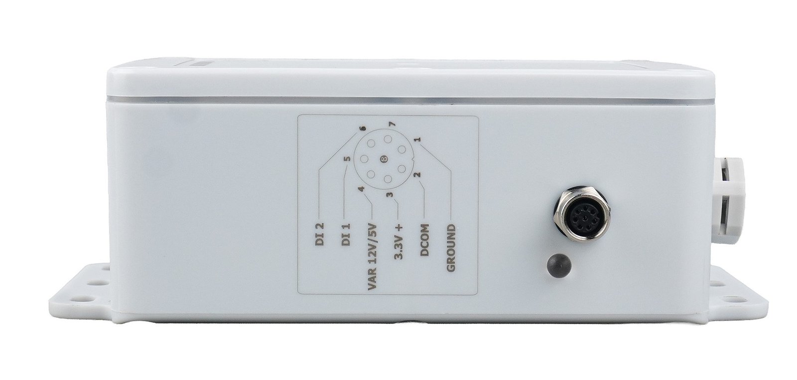
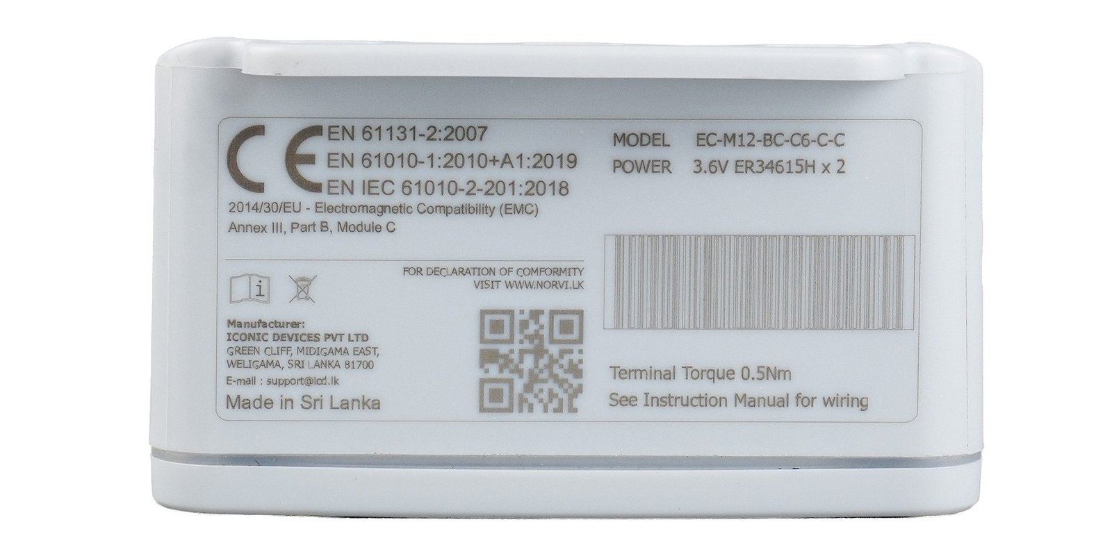
Start with the Model C datasheet for electrical limits and connector details, then use the quick-start and existing pulse-flow article for implementation context.
Practical answers for selecting a pulse counter data logger and connecting it to water, gas, energy or industrial flow meters.
A pulse counter data logger records electrical pulses from a meter or sensor, stores the count over time and can convert the total into engineering units using the meter's pulse value or K-factor. A connected logger can also transmit those totals to a remote server or dashboard.
Yes, when the meter's electrical pulse output is compatible with the EC-M12-BC-C6-C-C input circuit. Model C provides two digital inputs with selectable 3.3V, 5V and 12V input levels. The meter's output type, pulse width, maximum pulse rate and wiring requirements should be checked before installation.
Model C has two digital inputs, so firmware can count two compatible pulse sources independently. Confirm the electrical requirements and expected pulse rate for both meters before commissioning.
If the meter specifies a value such as “1 pulse = 10 litres,” multiply the pulse count by that value. If it specifies a K-factor such as “100 pulses per m³,” divide the pulse count by 100 to obtain cubic metres. Always use the scaling published for the exact meter configuration.
The current Model C datasheet lists the SIM7070 modem with LTE Cat-M1, NB-IoT (NB1/NB2) and GSM/GPRS 2G support. Band and operator availability varies by country, so carrier compatibility should be checked for the deployment location.
No claim is made here that EC-M12 itself is a revenue-grade measuring instrument. It counts pulses supplied by the connected meter. Billing or regulated metering applications depend on the meter, complete system design and local certification requirements.
Send NORVI the meter model, pulse-output specification, K-factor, expected maximum pulse rate, reporting interval and cellular region. That is enough to check whether EC-M12 Model C is the right fit and identify any interface requirements.
Due to a surge in global demand, our production queue is at full capacity. We will not accelerate production at the expense of quality - every device undergoes full CE / EMC compliance, regardless of order volume.
| Order Quantity | Lead Time | Notes |
|---|---|---|
| Under 10 units | 2-3 wks | Standard processing |
| 10 - 100 units | 4-5 wks | Mid-volume batch |
| Above 100 units | 6+ wks | Contact us for slot |