
Overview #
The NORVI X-UARTIO is a communication expansion module built for the NORVI X controller platform. It gives a single NORVI X CPU access to three industrial serial standards – RS485, RS232, and UART – so it can connect directly to Modbus RTU devices, PLCs, meters, sensors, and older RS232 equipment, without needing separate external converters for each one.
Rather than dedicating a fixed MCU pin to every port, the module shares a small set of MCU I/O lines across all ports and switches between them under firmware control (GPIO and chip-select-controlled routing). This keeps host pin usage low while still exposing four independent physical interface types.
Key Features #
- Three independent physical interface types
- Firmware-controlled interface routing
- Shared MCU I/O architecture
- GPIO- and chip-select-controlled switching
- Multiple serial communication options
- Reduced host MCU pin requirements
- Designed for NORVI expansion systems
Interface Types #
The UART-IO module provides four physical interface types:
| RS485 ports – half-duplex, differential, ideal for Modbus RTU | RS232 ports – full-duplex, legacy device connectivity | UART Ports – Serial communication with multiplexed routing for direct MCU connectivity. |
| Typical applications | Typical applications | Typical applications |
| ● PLCs and industrial controllers ● Modbus RTU devices ● Remote I/O modules ● Industrial sensors and instruments ● HMI and control panels | ● Industrial instruments ● HMIs ● Controllers ● PCs and serial equipment ● Legacy automation equipment | ● MCU-to-MCU communication ● Embedded peripherals ● Serial sensors ● Custom serial devices ● Debug and configuration interfaces |
Technical specifications #
| Parameter | Value |
|---|---|
| Supply Voltage | 24V DC |
| Current Consumption | 40mA @ 24V DC |
| Operating Temperature | –40 … +85° C |
| Dimensions / Mounting | DIN RAIL |
System Architecture #
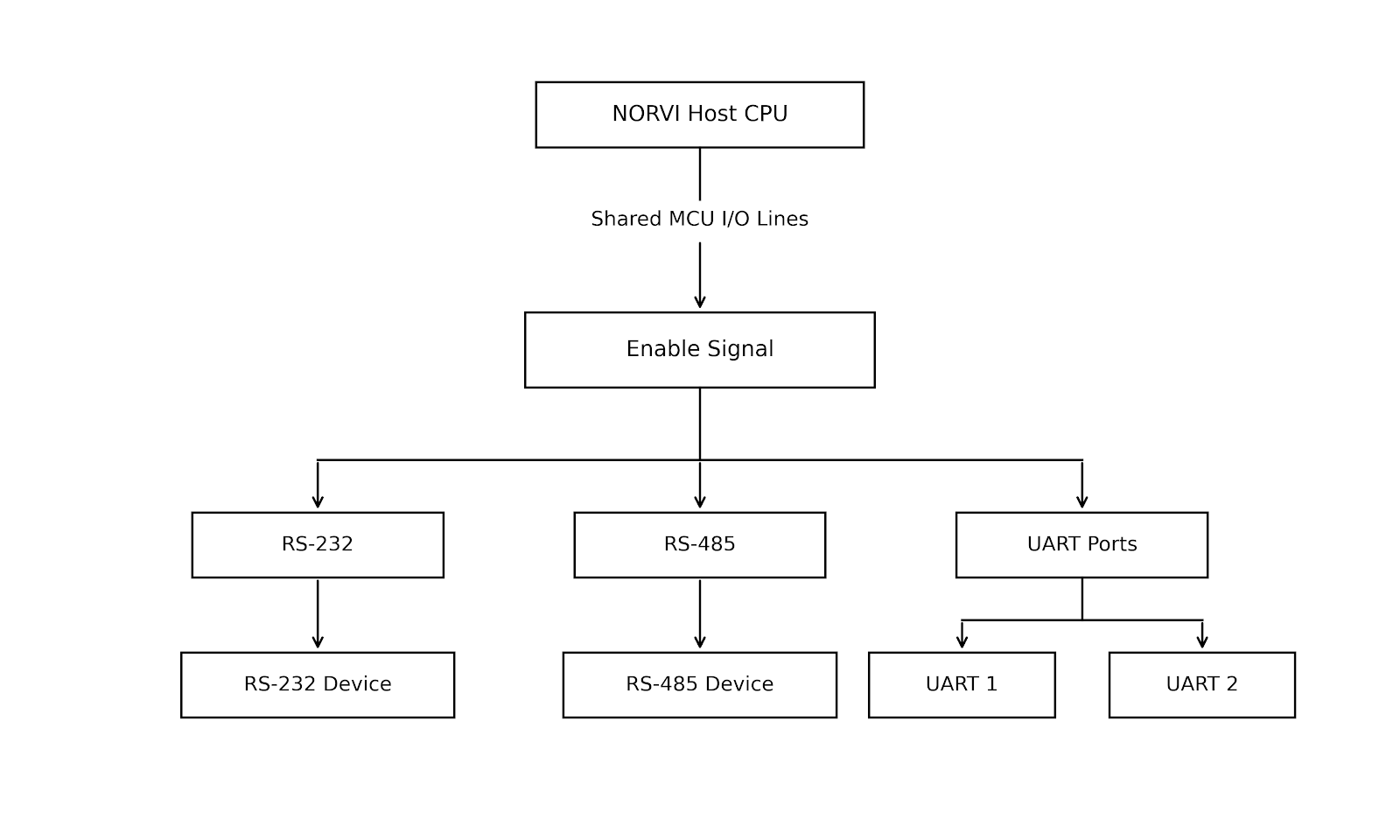
The UART-IO module uses a shared-I/O architecture rather than dedicating a separate MCU interface to every physical port.
The host MCU communicates with the module through a common set of I/O lines. Firmware controls the routing circuitry using Enable signals to connect the MCU interface to the required physical port.
Architecture Flow
This approach reduces the number of MCU pins required while allowing multiple physical communication interfaces to be available on the same expansion module.
Multiplexed Interface Operation #
The X-UARTIO uses two independent 4:2 multiplexers.
Each multiplexer provides a separate routing path between the shared MCU communication lines and two physical interfaces.
MUX 1 #
MUX 1 selects between:
- RS-485
- UART 1
MUX 2 #
MUX 2 selects between:
- RS-232
- UART 2
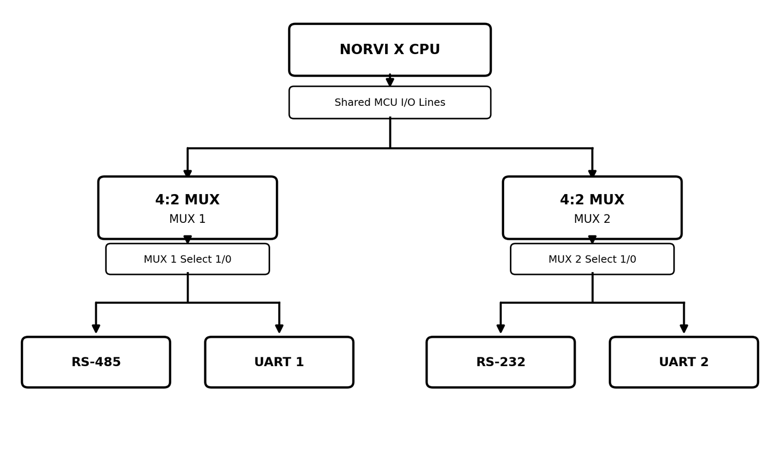
This architecture allows the host MCU to access the required physical interface without requiring a dedicated MCU interface for every port.
| MUX1 | MUX2 | Enabled Channel |
|---|---|---|
| 0 | RS485 (default) | |
| 1 | UART_1 | |
| 0 | RS232 (default) | |
| 1 | UART_2 |
RS-485 Interface #
The RS-485 interface uses differential signaling for reliable serial communication.
Interface Signals
| Signal | Function |
|---|---|
| A | Differential communication line |
| B | Differential communication line |
| GND | Ground |
Typical Connection
| X-UARTIO Expansion | RS-485 Device |
|---|---|
| A | A |
| B | B |
| GND | GND |
The actual wiring and termination requirements should follow the RS-485 network design and the module’s electrical specification.
GPIO Utilization
- RX: IO5
- TX: IO6
RS-232 Interface #
The RS-232 interface provides full-duplex serial communication.
Interface Signals
| Signal | Function |
|---|---|
| TX | Transmit Data |
| RX | Receive Data |
| GND | Ground |
Typical Connection
| X-UARTIO Expansion | RS-232 Device |
|---|---|
| TX | RX |
| RX | TX |
| GND | GND |
GPIO Utilization
- RX: IO7
- TX: IO10
UART Interface #
UART provides a serial TX/RX interface through MUX 1 or 2.
Interface Signals
| Signal | Function |
|---|---|
| TX | Transmit Data |
| RX | Receive Data |
| GND | Ground |
UART 1 shares the first multiplexed communication path with RS-485.
UART 2 shares the second multiplexed communication path with RS-232.
GPIO Utilization
UART – 1 #
- RX: IO5
- TX: IO6
UART – 2 #
- RX: IO7
- TX: IO10
MUX Selection and Firmware Control #
The multiplexed design reduces the number of host MCU pins required for the available interfaces.
Instead of using dedicated MCU communication lines for every physical port, the module shares communication signals through the multiplexers.
The firmware controls which physical interface is connected to the shared MCU communication lines.
General Operation #
- Configure the MUX selection GPIO.
- Select the required interface.
- Configure the communication peripheral.
- Start communication.
- Transmit and receive data.
- Change the MUX selection when another interface is required.
Interface Switching
Because the physical interfaces share communication resources, firmware must select the required interface before communication.
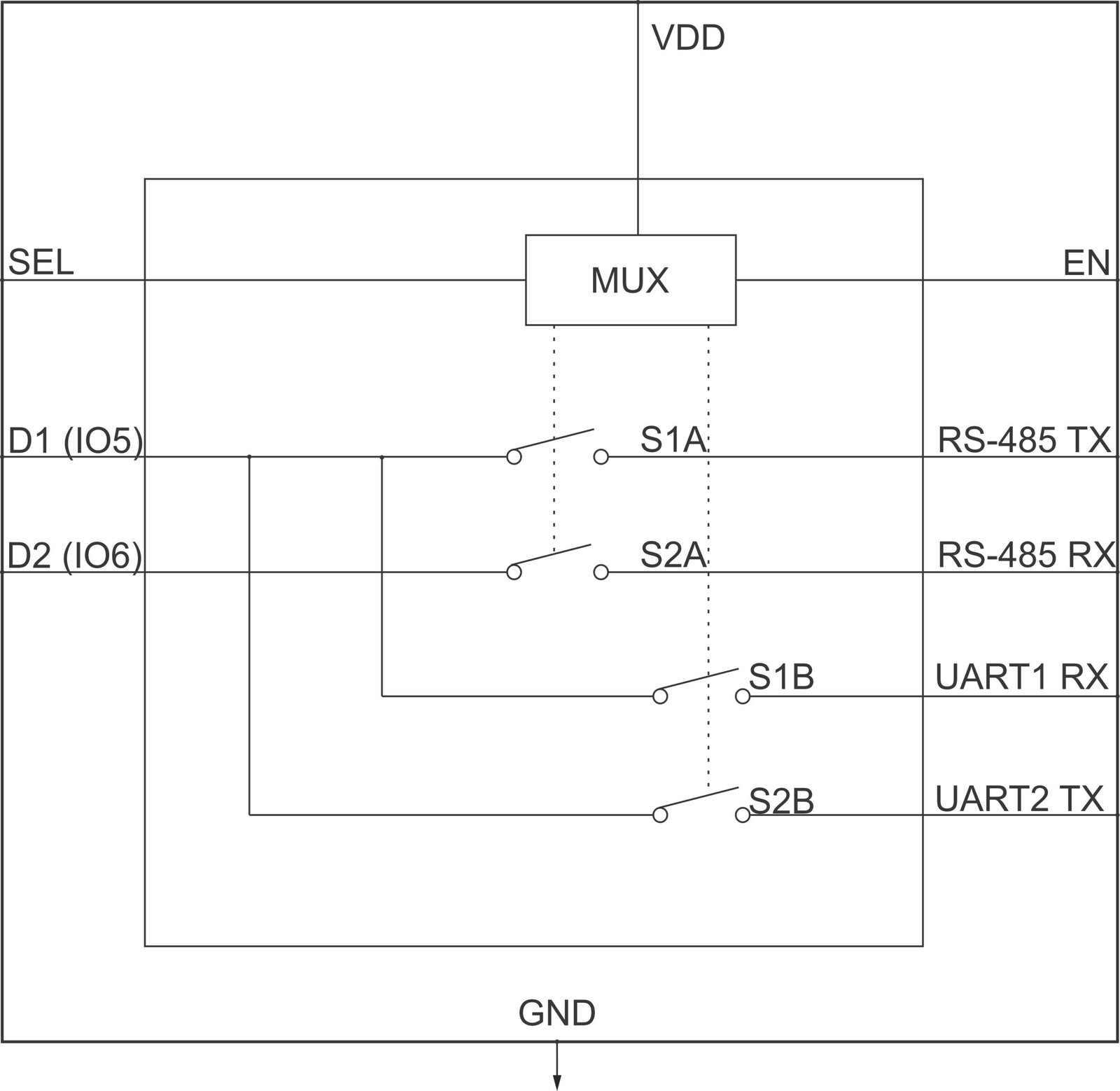
For example:
RS-485 to UART 1 Switching Procedure
- RS-485 is the default interface when MUX 1 is set to 0.
- Stop or complete the current RS-485 communication.
- Change MUX 1 Select from 0 to 1 through firmware.
- Configure the UART 1 communication parameters.
- Start UART 1 communication.
Note: Only one interface per multiplexed path can be active at a time – switch the MUX before starting the new interface, not while the previous one is still communicating.
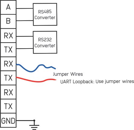
Wiring and Connection #
Provide separate wiring diagrams for:
- RS-485 connection
- RS-232 connection
- UART 1 connection
- UART 2 connection
- Host CPU to X-UARTIO connection
Programming Example #
Recommended Examples #
Example 1 – RS-485 Communication
- Connect the RS-485 device.
- Set MUX 1 Select to 0.
- Initialize the serial interface.
- Send data.
- Receive response.
Example 2 – UART A Communication
- Connect the UART device.
- Set MUX 1 Select to 1.
- Initialize the serial interface.
- Send and receive data.
Example 3 – RS-232 Communication
- Connect the RS-232 device.
- Set MUX 2 Select to 0.
- Initialize the serial interface.
- Send and receive data.
Example 4 – UART B Communication
- Connect the UART device.
- Set MUX 2 Select to 1.
- Initialize the serial interface.
- Send and receive data.
References and Supporting Documentation #
The following resources provide additional information for hardware configuration, interface selection, wiring, programming, and device operation.
Datasheet #
NORVI X-UARTIO Datasheet
Provides electrical specifications, interface details, pin assignments, and hardware configuration information.
User Guide #
NORVI X-UARTIO User Guide
Provides installation, wiring, configuration, interface selection, and operating procedures.
Arduino Example Code #
NORVI X-UARTIO Arduino Test Code
Provides a reference implementation for interface selection, MUX control, UART configuration, and serial communication.
The example code is available in the NORVI X-UARTIO GitHub repository.