
Overview #
NORVI X is a next generation modular industrial controller designed to power smart automation and IoT solutions. Built around a CPU module and a range of plug and play expansion modules, the platform scales from a handful of I/O points up to 200, giving system integrators, OEMs, and industrial engineers a flexible foundation for automation, remote monitoring, and data acquisition projects.
The NORVI X-LW is a LoRaWAN communication expansion module for the NORVI X modular controller platform, used for connecting controllers to LoRaWAN networks and remote monitoring systems. It is built around the RAK4630-9-SM-I LoRaWAN module with a Semtech SX1262 LoRa transceiver, which handles the radio communication and offloads timing-critical wireless processing from the main CPU. It enables long-range, low-power wireless communication, with an external antenna connection, regional LoRaWAN frequency band support, and a DIN rail enclosure rated for an operating temperature range of -40 to +85 °C, for reliable operation in industrial environments.
This guide covers everything needed to confidently install, wire, and commission the module, including safety requirements, technical specifications, terminal and address configuration, wiring steps, software setup, diagnostic test code, and troubleshooting.
Key Features #
- LoRaWAN wireless communication (LoRaWAN 1.0.3, plus LoRa P2P)
- RAK4630 LoraWAN Communication
- Long-range, low-power wireless connectivity
- Bluetooth 5.0 capability through the RAK4630 module
- I²C and UART expansion bus communication
- Plug and play connection to the CPU module through the expansion bus
- DIN rail mountable enclosure
- CE / EMC compliant (EN 61131-2:2007, EN 61010-1:2010+A1:2019, EN IEC 61010-2-201:2018, 2014/30/EU)
Safety Information #
Warning: Disconnect all power sources before installing, wiring, or servicing the NORVI X-LW. Failure to do so may result in electric shock or damage to the equipment.
General Safety #
- Install and wire this module only if you are a qualified electrician or trained technician familiar with industrial control equipment.
- Read the complete user guide before installation and operation.
- Do not operate the module with damaged connectors, cables, or antenna connections.
- Confirm the host CPU is running from a regulated 24 V DC supply, since the module draws its power through the expansion port rather than a separate connection.
- Mount the module on a DIN rail inside a suitably rated enclosure. It carries an IP20 protection rating and is not designed for direct outdoor or wash down exposure.
- Keep the operating environment within minus 40 to plus 85 degrees C and avoid condensing humidity.
- Do not connect or disconnect the module from the expansion bus while the system is powered.
- Follow all local and national electrical codes applicable to industrial control panel wiring.
Antenna Safety #
- Connect the appropriate antenna before operating the radio module.
- Do not operate the radio module without a properly connected antenna.
- Keep the antenna away from sensitive electronic equipment where applicable.
- Comply with applicable local RF regulations for the selected frequency band and transmission power.
Industrial Installation #
- Verify communication and wiring changes on a test setup before connecting the controller to active industrial equipment.
- Ensure all wiring and configuration changes are completed with the equipment in a safe condition.
- Follow the safety requirements of the connected industrial equipment and installation.
Technical Specifications #
Electrical #
| Rated Supply Voltage | 24V DC |
| Current Consumption | 40mA @ 24V DC |
General Specifications #
| Parameter | Specification |
|---|---|
| Wireless module | RAK4630 |
| LoRa transceiver | Semtech SX1262 |
| Host interface | UART / I2C |
| UART baud rate | 115200 |
| UART data format | 8-N-1 |
| Wireless technology | LoRa / LoRaWAN |
UART Specifications #
| Parameter | Value |
|---|---|
| Baud rate | 115200 |
| Data bits | 8 |
| Parity | None |
| Stop bits | 1 |
| ESP32-S3 RX | GPIO 14 |
| ESP32-S3 TX | GPIO 40 |
UART Connection #
| ESP32-S3 | RAK Module |
|---|---|
| GPIO 40 / TX | RX / P0.15 |
| GPIO 14 / RX | TX / P0.16 |
| GND | GND |
Hardware Layout #
Hardware Overview #
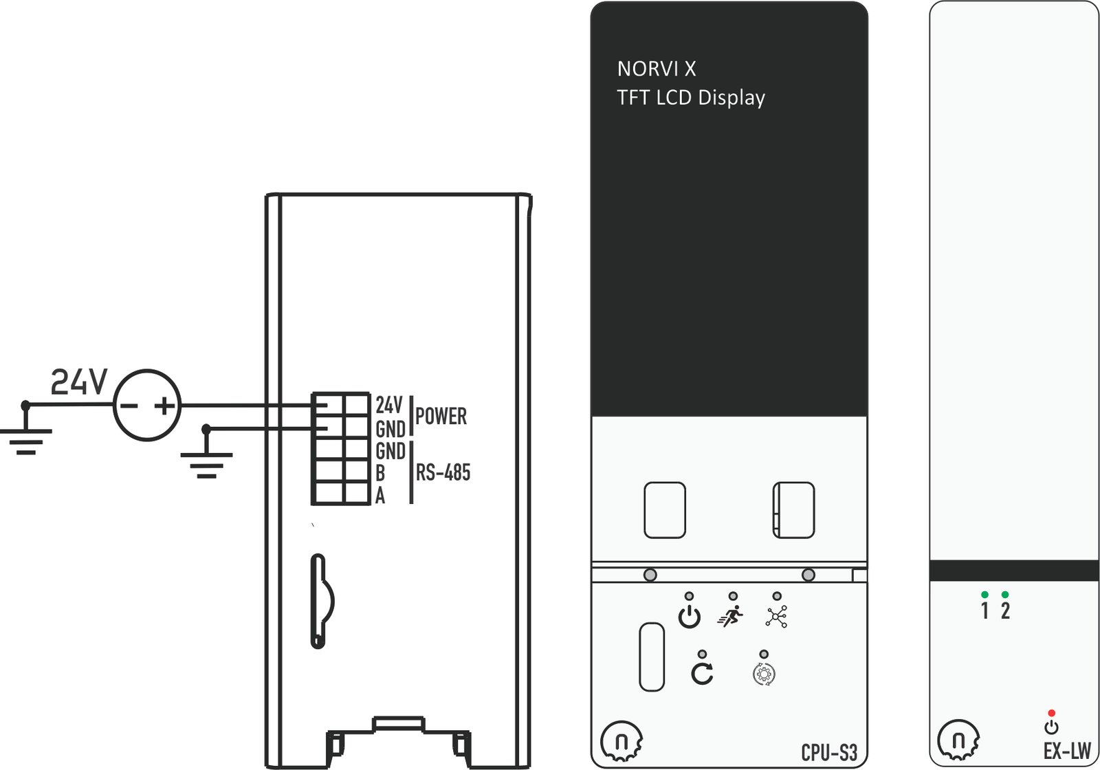
The NORVI X-LW is a LoRaWAN expansion module in the NORVI X-N1 enclosure. It mounts on a DIN rail beside the NORVI X CPU and connects through the 50-pin expansion bus. The CPU powers it, and the on-board RAK4630 module handles the LoRa and LoRaWAN radio.
- NORVI X-LW
- RAK4630 module
- Antenna connector
- Host connector
- UART connections
- Power connections
- Mounting locations
LED Indicators #
| LED | Colour | Behaviour |
|---|---|---|
| Power | Red | Power Indicator |
| LED1 | Green | User Configurable Indicators |
| LED2 | Green | User Configurable Indicators |
Wiring Guide #
GPIO pin assignments for every input are listed in the Hardware Layout and GPIO Map section below; this section covers how to physically wire the module, not the pin numbers themselves.
Connecting the Module to the CPU #
- Power off the system.
- Mount the X-LW on the DIN rail next to the CPU module or an adjacent expansion module.
- Power the system back on.
- Upload the master code to the CPU and the slave code to the expansion module from the NORVI GitHub repository to confirm communication and operation before integrating the module into your final control logic.
Expansion Port (50 pin) #
Utilized GPIO Connections are highlighted in Green. They cannot be used for any other purpose with this module connected. The X-LW connects to the CPU through the shared 50 pin expansion bus.
| PIN INDEX | Purpose | GPIO | SOURCE |
|---|---|---|---|
| 1 | MOSI | IO11 | ESP32-S3 |
| 2 | MISO | IO13 | |
| 3 | SCLK | IO12 | |
| 4 | GND | —- | |
| 5 | SCL | IO9 | |
| 6 | SDA | IO8 | |
| 7 | GND | —- | |
| 8 | RX1 | IO18 | |
| 9 | TX1 | IO17 | |
| 10 | GND | —- | |
| 11 | D+ | —- | |
| 12 | D- | —- | |
| 13 | GND | —- | |
| 14 | CS1 | P1_0 | PCA9539 I2C Address 0x75 |
| 15 | CS2 | P0_7 | |
| 16 | CS3 | P0_6 | |
| 17 | CS4 | P0_5 | |
| 18 | IO1 | IO1 | ESP32-S3 |
| 19 | IO2 | IO2 | |
| 20 | IO4 | IO4 | |
| 21 | IO5 | IO5 | |
| 22 | IO6 | IO6 | |
| 23 | IO7 | IO7 | |
| 24 | IO10 | IO10 | |
| 25 | IO11 | IO35 | |
| 26 | IO12 | IO36 | |
| 27 | IO13 | IO37 | |
| 28 | IO14 | IO14 | |
| 29 | RS485_TX | IO15 | |
| 30 | GND | —- | |
| 31 | GND | —- | |
| 32 | RS485_RX | IO16 | |
| 33 | P1_1 | P1_1 | PCA9539 I2C Address 0x75 |
| 34 | P1_2 | P1_2 | |
| 35 | IO21 | IO21 | ESP32-S3 |
| 36 | GND | —- | |
| 37 | GND | —- | |
| 38 | P1_3 | P1_3 | PCA9539 I2C Address 0x75 |
| 39 | P1_4 | P1_4 | |
| 40 | P1_5 | P1_5 | |
| 41 | IO39 | IO39 | ESP32-S3 |
| 42 | IO40 | IO40 | |
| 43 | NC | —- | |
| 44 | NC | —- | |
| 45 | NC | —- | |
| 46 | GND | —- | |
| 47 | 5V | 5V | |
| 48 | GND | GND | |
| 49 | 24V | 24V | |
| 50 | 24V | 24V |
Software Setup (Arduino IDE) #
The NORVI X-LW is controlled by the host CPU. The host CPU uses the ESP32 board package, while the RAK4630-based X-LW uses the RAKwireless board package. Firmware examples and the required libraries are maintained in the NORVI GitHub repository.
The NORVI X system has two programmable devices, and each one needs its own code and board selection.
| Device | Code | Board selection (Tools → Board) |
|---|---|---|
| NORVI X CPU (ESP32-S3) | Master code | ESP32 Arduino → ESP32S3 Dev Module |
| NORVI X-LW | Slave code | RAKwireless RUI nRF Boards → WisBlock Core RAK4631 Board |
- Upload the master code to the CPU and the slave code to the X-LW, each as a separate upload.
- Change the board and port in the Tools menu every time you switch devices.
Required Software #
- Arduino IDE
- ESP32 board packages
- ArduinoJson library
- RAK module board packages installed
- Test codes
Arduino IDE Configuration #
Master Code to NORVI X-CPU #
ESP32 Board Selection
- Install Arduino IDE
Install the Arduino IDE and add ESP32 board support:
Tools → Board → Boards Manager → ESP32
- Connect the Controller
Connect the NORVI X CPU to your computer using the USB interface.
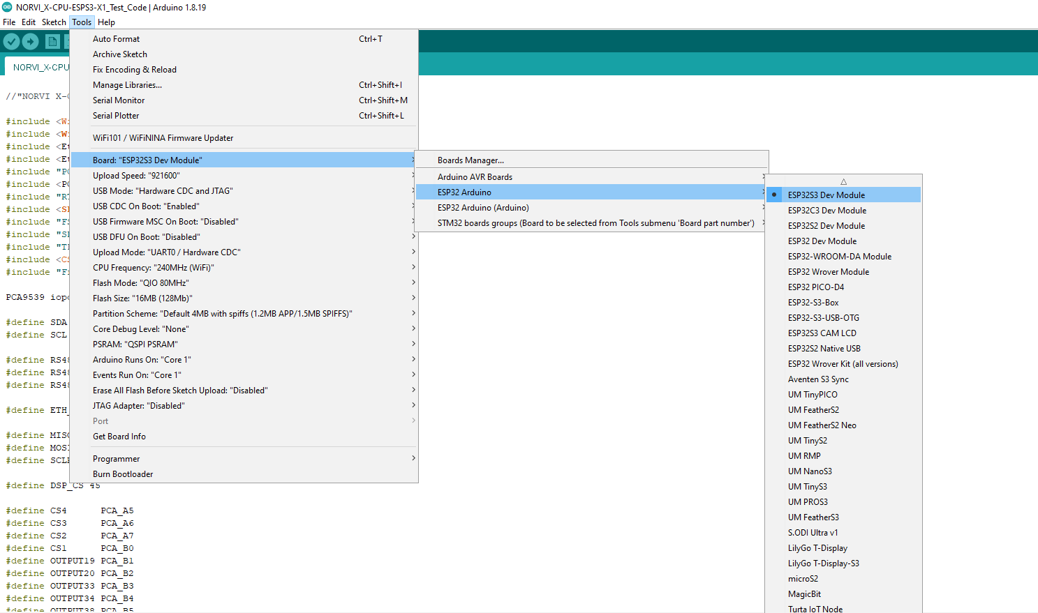
- Select Board and Port
Configure the board and communication port:
- Tools → Board → ESP32 Arduino → ESP32S3 Dev Module
- Tools →Port → Select the corresponding COM/serial port
- Configure Board Settings
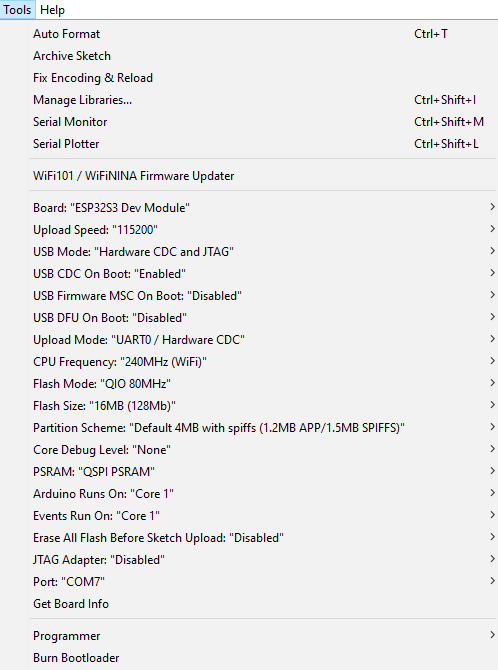
Under the Tools menu, configure the following settings:
| Setting | Selection |
|---|---|
| USB CDC On Boot | Enabled |
| Flash Size | 16MB (128Mb) |
| PSRAM | QSPI PSRAM |
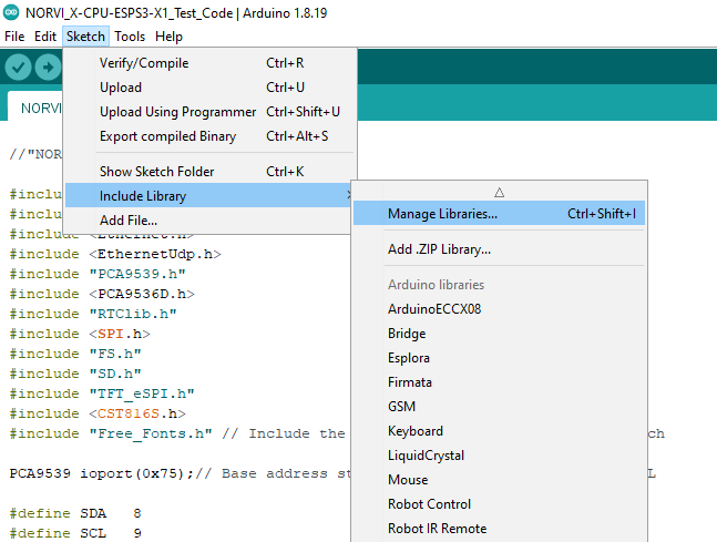
Install ArduinoJson
The master example uses:
#include <ArduinoJson.h>Install the ArduinoJson library through the Arduino IDE Library Manager.
Sketch → Include Library → Manage Libraries
Search for Wire and install it if required.
The Libraries are available in the NORVI-X-Version-02 GitHub repository.
Slave Code to NORVI X-LW #
RAK4630 Module Selection
Select Board and Port
Configure the board and communication port:
- Tools → Board → RAKwireless RUI nFR Boards → WisBlock Core RAK4631 Board
- Tools →Port → Select the corresponding COM/serial port
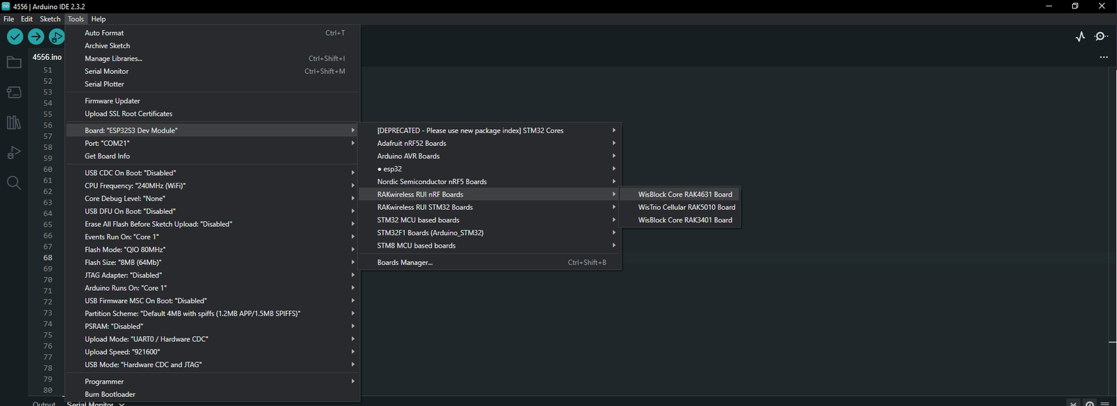
For more information on installing and configuring the RAK4630 module, refer to the RAK4630 Module Quick Start Guide.
Test Code Examples #
Master Test Code #
Purpose
The master test code demonstrates communication between the ESP32-S3 and the RAK module.
- Initializes UART communication.
- Generates two random values.
- Creates a JSON message.
- Send the JSON message to the LW expansion.
- Displays the transmitted data on the USB Serial Monitor.
- Checks for a response.
- Repeat the process every 30 seconds.
Host-to-RAK Communication #
The ESP32-S3 communicates with the RAK module using UART.
The master code defines:
#define LoRaSerial Serial1
#define LORA_RX_PIN 14
#define LORA_TX_PIN 40
The UART is initialized at:
115200, SERIAL_8N1The example uses:
Serial.begin(115200);for USB/debug output and:
LoRaSerial.begin(115200, SERIAL_8N1, LORA_RX_PIN, LORA_TX_PIN);for communication with the RAK module.
JSON Data Format #
- The master generates two dummy values:
int Analog1 = random(0, 101);  // Analog1 is a dummy value
int Analog2 = random(0, 101); //Analog2 is a is dummy value- These values are placed into a JSON object:
jsonDocument["Analog1  "] = Analog1;
jsonDocument["Analog2 "] = Analog2;- The resulting message has the following structure:
{"Analog1":45,"Analog2":72}The actual values change during each transmission.
- Display Transmission
Serial.print("TX -> ");
Serial.println(jsonString);- Receive Response
while (LoRaSerial.available())
{
    String receivedString = LoRaSerial.readStringUntil('\n');

    Serial.print("RX <- ");
    Serial.println(receivedString);
}- Transmission Interval
delay(30000);The test code therefore sends a new test message approximately every 30 seconds.
Message Transmission #
The JSON string is sent through UART using:
LoRaSerial.println(jsonString);println() adds a newline at the end of the message.
Therefore, the receiving code can use newline-based message handling.
Slave Test Code #
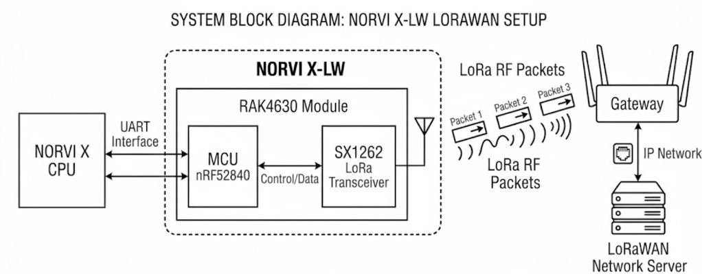
The RAK4630 Slave Test Code configures the RAK4630 for LoRaWAN communication, joins the LoRaWAN network using OTAA, receives data from the NORVI X CPU through UART, and sends the received data as a LoRaWAN uplink.
Code Communication Flow
The main operation of the Slave Test Code is:
LoRaWAN Configuration #
The test code uses OTAA for network activation. The LoRaWAN region can be selected in the code by uncommenting the required region definition and commenting out the other region definitions. The example is configured for EU868 by default.
#define OTAA_BAND (RAK_REGION_EU868)
#define OTAA_DEVEUI { /* Device EUI */ };
#define OTAA_APPEUI { /* Application EUI / JoinEUI */ };
#define OTAA_APPKEY { /* Application Key */ };
The parameters are used as follows:
| Parameter | Description |
|---|---|
| OTAA_BAND | LoRaWAN frequency region |
| OTAA_DEVEUI | Device EUI of the RAK4630 |
| OTAA_APPEUI | Application EUI / JoinEUI |
| OTAA_APPKEY | Application Key used for OTAA authentication |
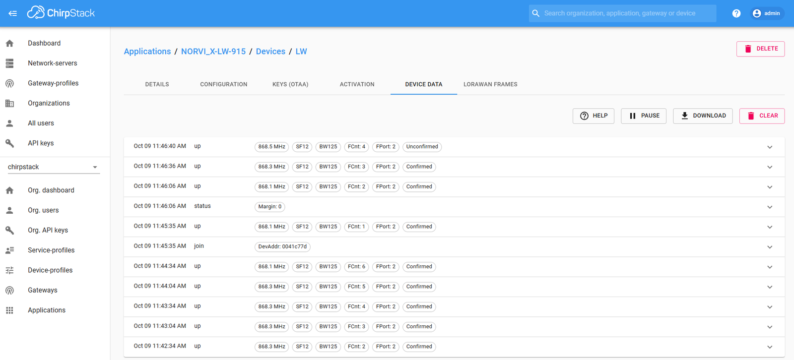
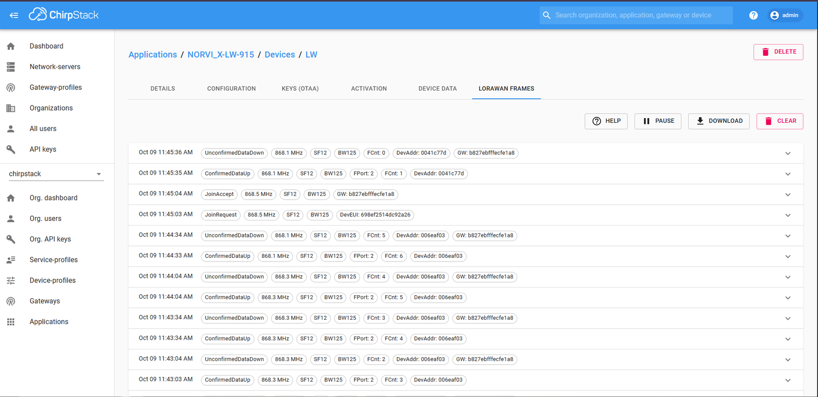
Note: Configure the Device EUI (DevEUI), Application EUI (JoinEUI/AppEUI), and Application Key (AppKey) according to the LoRaWAN network server or platform being used. The test codes have been tested and verified with ChirpStack, but they can also be used with other compatible LoRaWAN network servers and platforms. Keep the Application Key confidential.
UART Configuration #
The RAK4630 communicates with the NORVI X CPU through Serial1 at 115200 baud.
Serial1.begin(115200);The NORVI X CPU sends the application data through this UART connection.
LoRaWAN Mode and Device Configuration #
The code configures the RAK4630 for LoRaWAN operation.
api.lorawan.nwm.get();
api.lorawan.nwm.set();
The OTAA credentials are loaded into the LoRaWAN configuration:
uint8_t node_device_eui[8] = OTAA_DEVEUI;
uint8_t node_app_eui[8] = OTAA_APPEUI;
uint8_t node_app_key[16] = OTAA_APPKEY;

api.lorawan.appeui.set(node_app_eui, 8);
api.lorawan.appkey.set(node_app_key, 16);
api.lorawan.deui.set(node_device_eui, 8);
api.lorawan.band.set(OTAA_BAND);
The device class and OTAA join mode are configured as follows:
api.lorawan.deviceClass.set(RAK_LORA_CLASS_A);
api.lorawan.njm.set(RAK_LORA_OTAA);
Joining the LoRaWAN Network #
The RAK4630 starts the OTAA join procedure using:
api.lorawan.join(1, 0, 10, 8);The join callback monitors the join result:
void joinCallback(int32_t status)
{
Serial.printf("Join status: %d\r\n", status);

if (status != 0) {
    joinFailed = true;
    }
}
The code waits until the device successfully joins the LoRaWAN network before continuing with normal operation.
LoRaWAN Transmission Configuration #
After joining the network, the code enables Adaptive Data Rate (ADR), configures the retry count, and enables confirmed uplinks.
api.lorawan.adr.set(true);
api.lorawan.rety.set(1);
api.lorawan.cfm.set(1);
The code also reads and displays the assigned device address:
uint8_t assigned_dev_addr[4] = { 0 };
api.lorawan.daddr.get(assigned_dev_addr, 4);
Receiving Data from the NORVI X CPU #
The RAK4630 continuously checks Serial1 for data from the NORVI X CPU.
while (Serial1.available()) {
inputString_Str = Serial1.readStringUntil('\n');
stringComplete = true;
}
A complete message is identified when a newline character is received.
For example, the NORVI X CPU can send:
{"Analog1":45,"Analog2":72}The received message is then passed to the uplink function:
uplink_routine(inputString);Preparing the Uplink Payload #
The uplink_routine() function copies the received UART data into the LoRaWAN transmission buffer.
uint8_t collected_data[64] = { 0 };The received data is copied into the buffer:
size_t len = strlen(json_str);
if (len > sizeof(collected_data))
len = sizeof(collected_data);
memcpy(collected_data, json_str, len);
uint8_t data_len = (uint8_t)len;
The buffer can hold up to 64 bytes. Data longer than the buffer is limited to the buffer size.
Sending the LoRaWAN Uplink #
The prepared data is sent using the RAK LoRaWAN API:
api.lorawan.send( data_len, (uint8_t*) &collected_data, 2, true, 1 );The JSON message received from the NORVI X CPU is used as the LoRaWAN application payload.
Transmission Status #
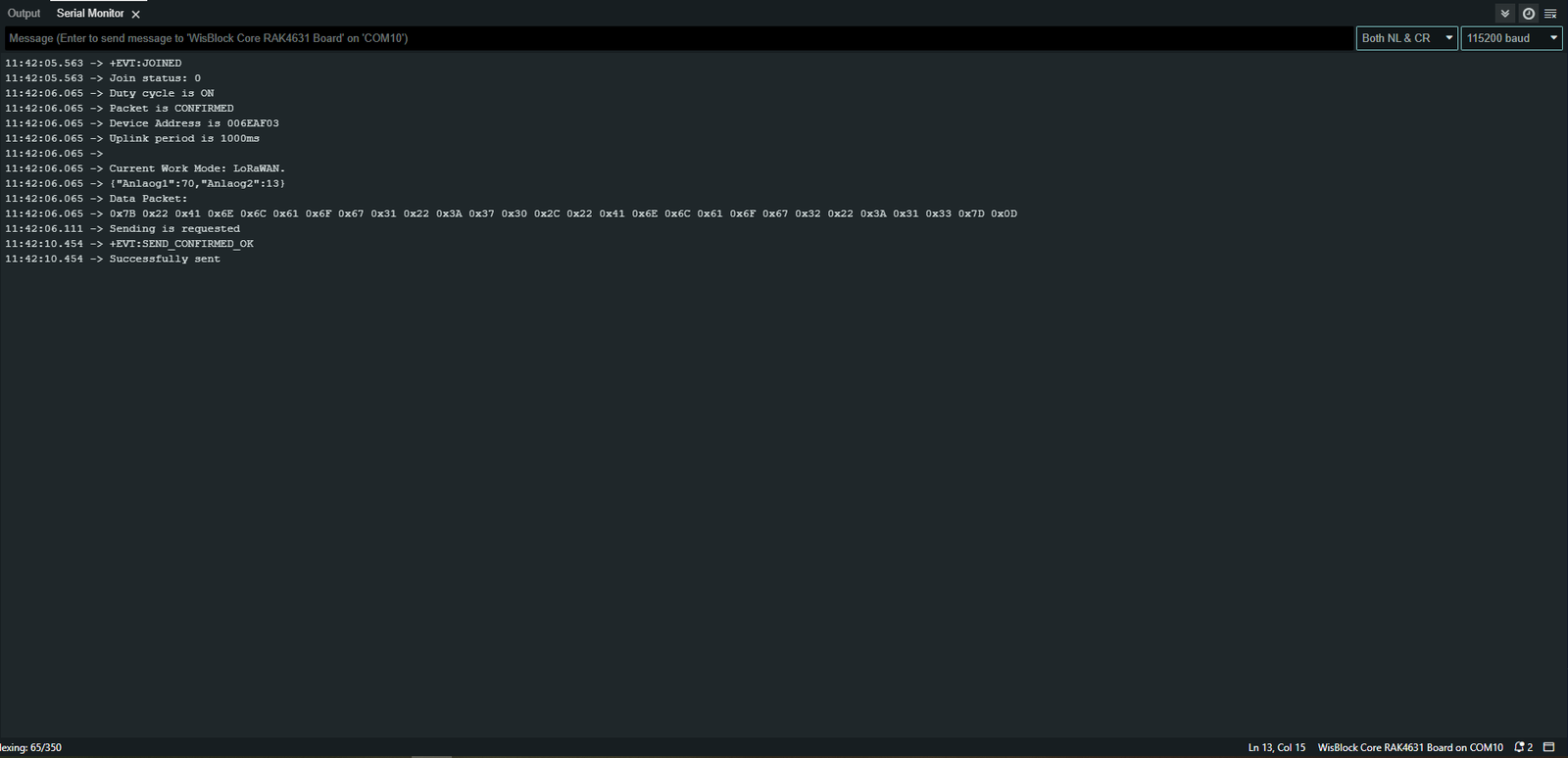
The send callback reports the result of the uplink transmission.
void sendCallback(int32_t status)
{
    if (status == 0) {
        Serial.println("Successfully sent");
        ledPulse(LED_GREEN, 150);
    } else {
        Serial.println("Sending failed");
        ledPulse(LED_BLUE, 300);
        }
}
The Serial Monitor displays:
Troubleshooting #
| Problem | Possible Cause | Check |
|---|---|---|
| No output on Serial Monitor | Incorrect COM port or baud rate | Check COM port and 115200 baud |
| ESP32 does not upload | Incorrect board/port selection | Check Arduino IDE settings |
| Garbled UART data | Baud-rate mismatch | Verify 115200 baud on both sides |
| JSON not received correctly | Message handling mismatch | Check newline/message parsing |
| No LoRa data received | Wireless configuration mismatch | Check the actual LoRa configuration |
| Slave does not respond | Slave code/configuration issue | Check slave Serial Monitor/output |
| No wireless transmission | RAK module configuration or hardware issue | Check module, antenna and configuration |
| Intermittent communication | Wiring, power or RF conditions | Check connections and installation |