
Applies to NORVI X-DI4 and NORVI X-DI8
The X-DI4 and X-DI8 both take external field signals, isolate them, and hand them to the controller as clean digital states. But they’re built with different priorities. The X-DI4 gets the signal to the CPU as fast and directly as possible, with nothing in between. The X-DI8 trades away some of that speed so you can add far more inputs without using up the controller’s limited GPIO pins. Neither is better; they’re built for different jobs. The real question is what your application needs: a few inputs that must react in microseconds, or many inputs that just need to report their state reliably.
The Core Difference in One Sentence #
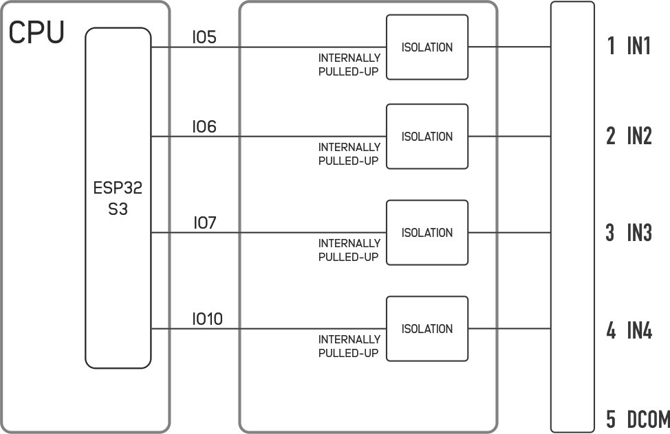
- X-DI4 wires each input straight to a dedicated microcontroller GPIO through a fast photo-IC optocoupler – built for speed.
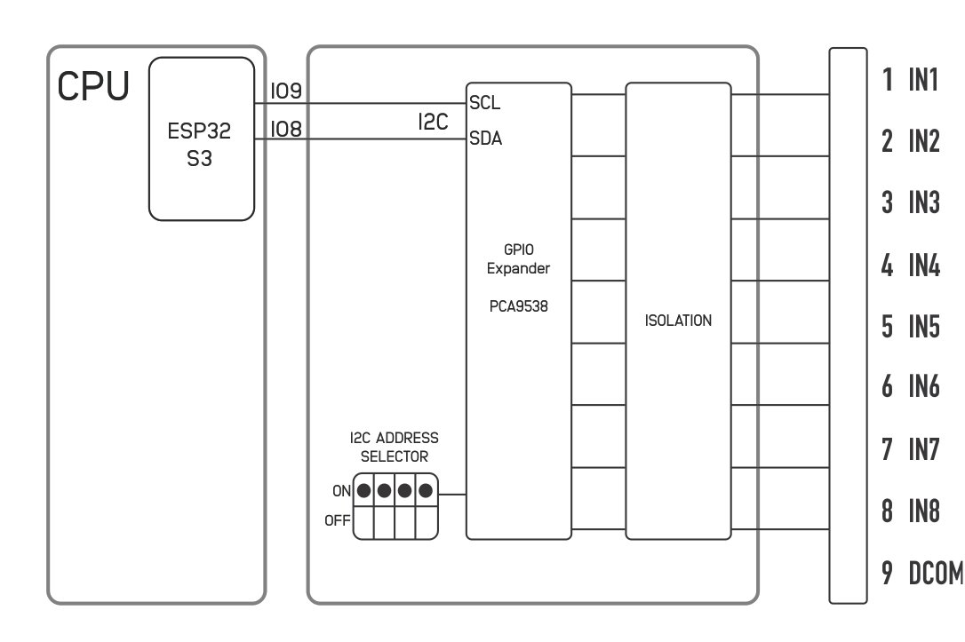
- X-DI8 reads its inputs through an I²C port expander behind a slower phototransistor optocoupler – built for scale.
Hardware Architecture #
X-DI4 – Direct GPIO
| Item | Detail |
|---|---|
| Optocoupler | 4 × TLP2361_E (photo-IC output, one channel per chip) |
| Signal path | Optocoupler → directly wired to GPIO |
| GPIO pins used | IN1→IO5, IN2→IO6, IN3→IO7, IN4→IO10 |
| Max inputs | 4 (fixed – one module per controller, since it consumes dedicated pins) |
The TLP2361 isn’t a basic optocoupler, it’s a smarter chip. Normally, an optocoupler just gives you a weak signal that needs extra parts to turn into a clean digital 0/1. The TLP2361 does that job itself, inside the chip: it takes the light signal and outputs a ready-to-use digital HIGH or LOW directly. So you can wire it straight to a GPIO with no extra circuitry needed which is also why it responds so fast.
X-DI8 – I²C Port Expander
| Item | Detail |
|---|---|
| Optocoupler | 2 × TLP290-4 (4-channel phototransistor package each → 8 channels total) |
| Signal path | Optocoupler → PCA9538 I²C port expander → SDA/SCL |
| GPIO pins used | Only IO8 (SDA) / IO9 (SCL) – shared bus |
| I²C addresses | 0x70–0x73, set by onboard DIP switches |
| Max inputs | Up to 4 modules stacked on one bus → 32 inputs from 2 pins |
The TLP290-4 is a basic optocoupler, just an LED and a phototransistor, nothing smarter. Its output isn’t a clean digital signal, it’s just a weak current that changes with light. So before the PCA9538 can read it as a proper 0 or 1, it needs extra parts (pull-up resistors) to shape that current into a real digital signal. The TLP2361 skips this step entirely, which is one reason DI8 ends up slower than DI4.
Why the Speed Gap Exists (It’s Two Compounding Factors) #
It’s tempting to think DI4 is fast simply because it skips the I²C bus. That’s true, but it’s only half the reason. The other half is that DI4 and DI8 use different types of optocouplers – and one is a faster class of chip than the other.
| Factor | X-DI4 (TLP2361_E) | X-DI8 (TLP290-4) |
|---|---|---|
| Optocoupler class | Photo-IC – fast, built-in digital output | Phototransistor – slower, needs extra parts to clean up the signal |
| Typical switching time | Data rate 15 MBd; effective board-level switching up to ~5 kHz | ton/toff ≈ 2–3 µs per transition, further limited by I²C polling to ~1 kHz |
| Path to CPU | Direct wire to GPIO – near-zero added latency | Through PCA9538 register → I²C read → CPU – each read is a full bus transaction |
Bottom line: DI4 is fast for two reasons: it uses a faster chip, and it skips the bus. DI8 is slower for the same two reasons in reverse: it uses a slower chip, and it goes through the bus. Both effects add up together, so it’s not just “wired vs. bus,” it’s “fast chip and wired” vs. “slow chip and bus.”
Side-by-Side Summary #
| Spec | X-DI4 | X-DI8 |
|---|---|---|
| Optocoupler | 4 × TLP2361 (photo-IC) | 2 × TLP290-4 (phototransistor, 4-ch each) |
| Interface | Direct GPIO | I²C via PCA9538 |
| GPIO pins consumed | 4 dedicated pins | 2 shared pins (SDA/SCL) |
| Max channels per controller | 4 (one module only) | 32 (4 modules stacked) |
| Practical switching speed | ~5 kHz | ~1 kHz |
| Isolation voltage | 3750 Vrms | 2500 Vrms |
| Operating temperature | -40 to 125 °C | -55 to 110 °C |
| Best for | PWM signals, encoders, pulse counting, frequency-sensitive inputs | Switch status, sensor states, alarms — anything that doesn’t need to be fast but needs to scale |
Choosing Between X-DI4 and X-DI8 #
Pick X-DI4 when:
- You’re reading a pulse train, encoder, flow meter, or PWM signal.
- Timing accuracy matters – you can’t afford I²C polling latency.
- You only need 4 or fewer fast inputs.
Pick X-DI8 when:
- You’re reading simple on/off states – limit switches, door sensors, relay feedback, dry contacts.
- You need more than 4 inputs and want to conserve GPIOs.
- Switching speed in the sub-kHz range is more than fast enough for your process.