
Overview #
NORVI X is a next generation modular industrial controller designed to power smart automation and IoT solutions. Built around a CPU module and a range of plug and play expansion modules, the platform scales from a handful of I/O points up to 200, giving system integrators, OEMs, and industrial engineers a flexible foundation for automation, remote monitoring, and data acquisition projects.
The NORVI X-MX4-CI is a mixed I/O expansion module for the NORVI X modular controller. It combines 4 isolated 24 V DC digital inputs, 4 transistor outputs, and 4 analog current inputs (4–20 mA / 0–20 mA) in a single DIN rail module, so you can monitor switches and sensors, drive field devices, and measure process signals without adding separate modules for each job. The digital inputs and the 16-bit ADS1115 analog converter are read by the NORVI X CPU over the internal I2C expansion bus, with DIP switches selecting the I2C addresses so that several modules can share one controller.
This guide covers everything needed to confidently install, wire, and commission the module, including safety requirements, technical specifications, terminal and address configuration, wiring steps, software setup, diagnostic test code, and troubleshooting.

A faster way to test your hardware
Test your NORVI X-MX4-CI.
Skip the setup. #
The test code for your NORVI X-MX4-CI is already written and ready in Neural Studio(Arduino Compiler on the browser). Open the project to compile and flash your device, manually or with AI assistance. Then edit the same code for your own application, no need to start from scratch or install Arduino IDE and libraries.
Key Features #
- 4 × isolated 24 V DC digital inputs with per-channel LED indicators
- 4 × high-side transistor outputs (P-channel MOSFET), 0.5 A per channel, with per-channel resettable PTC fuse and LED indicators
- 4 × analog inputs, 4–20 mA / 0–20 mA, measured by a 16-bit ADS1115 ADC
- Optocoupler isolation per channel on digital inputs and transistor outputs
- Over-voltage, reverse polarity, and ESD protection on the digital inputs
- Selectable I2C addresses for the analog and digital sections through DIP switches
- DIN rail mountable enclosure with spring terminals
- Plug and play connection to the CPU module through the expansion bus
- CE / EMC compliant (EN 61131-2:2007, EN 61010-1:2010+A1:2019, EN IEC 61010-2-201:2018, 2014/30/EU)
Safety Information #
Warning: Disconnect all power sources before installing, wiring, or servicing the NORVI X-MX4-CI. Failure to do so may result in electric shock or damage to the equipment.
- Install and wire this module only if you are a qualified electrician or trained technician familiar with industrial control equipment.
- Confirm the host CPU is running from a regulated 24 V DC supply, since the module draws its power through the expansion port rather than a separate connection.
- Mount the module on a DIN rail inside a suitably rated enclosure. It carries an IP20 protection rating and is not designed for direct outdoor or wash down exposure.
- Keep the operating environment within minus 40 to plus 85 degrees Celsius and avoid condensing humidity.
- Do not connect or disconnect the module from the expansion bus while the system is powered.
- Follow all local and national electrical codes applicable to industrial control panel wiring.
Technical Specifications #
Electrical #
| Rated Supply Voltage | 24V DC |
| Current Consumption | 2500mA @ 24V DC |
Digital Input Specifications #
| Parameter | Specification |
|---|---|
| Number of Inputs | 4 Digital Inputs |
| Input Type | Isolated 24 V DC |
| Isolation Voltage | > 1500 Vrms (optical isolation from CPU) |
| Input Voltage Range | 0 – 30 V DC |
| Logic Low (OFF) | < 5 V DC |
| Logic High (ON) | > 15 V DC |
| Input Impedance | Approx. 3.3 kΩ |
| Input Current | ~ 7 mA @ 24 V DC |
| Switching Frequency | Up to 1 kHz |
| Protection | Over-voltage, Reverse Polarity, ESD Protected |
| Isolation Type | Opto-coupler isolation per channel |
| Interface to CPU | NORVI X Expansion Port (Direct GPIO) |
| Status Indicators | 4 × LED Input Indicators |
| Power Supply | 24 V DC (shared with CPU via expansion port) |
| Communication Bus | Internal Expansion Bus |
| Connector Type | Push-in Terminal Block |
Transistor Outputs Specifications #
| Parameter | Specification |
|---|---|
| Number of Outputs | 4 Transistor Output Channels |
| Transistor Output Current | 0.5A |
| Maximum Supply Voltage | 24V DC |
| Maximum Supply Current | 4 – 5A |
| Output Type | High-Side Switch |
| Switching Transistor | P-Channel MOSFET |
| Isolation Type | Optocoupler Isolation |
| Protection (Per Channel) | Per-Channel Resettable PTC Fuse ● Hold Current: 0.5 A at 20°C ● Trip Current: 1 A |
| Output Diagnostics | Individual LED indicators |
| Field Connector | 4-Pin Terminal Block |
Analog Inputs Specifications #
| Number of Analog Inputs | 4 |
| Analog Input Measurement Range | 4 – 20mA / 0 – 20mA |
| Analog to Digital Converter (ADC) | ADS1115 |
| Analog to Digital Converter (ADC) Resolution | 16-bit |
| Analog to Digital Converter (ADC) Communication | I2C |
| ADC Power Supply | 3.3V |
Hardware Layout & GPIO Map #
The table below lists the 18 front terminals of the X-MX4-CI. The module shares only the I2C bus (SCL and SDA) with the host CPU, so the digital inputs, transistor outputs, and analog inputs do not claim any other CPU GPIO pins for themselves..
| No. | Terminal | Description |
|---|---|---|
| 1 | IN1 | Digital Input 1 |
| 2 | IN2 | Digital Input 2 |
| 3 | IN3 | Digital Input 3 |
| 4 | IN4 | Digital Input 4 |
| 5 | DCOM | Isolated Digital Ground |
| 6 | TR1 | Transistor Output 1 |
| 7 | TR2 | Transistor Output 2 |
| 8 | TR3 | Transistor Output 3 |
| 9 | TR4 | Transistor Output 4 |
| 10 | GND | Ground |
| 11 | AIN1 | Analog Input 1 |
| 12 | AIN2 | Analog Input 2 |
| 13 | AIN3 | Analog Input 3 |
| 14 | AIN4 | Analog Input 4 |
| 15 | AGND | Analog Ground |
| 16 | GND | Ground |
| 17 | GND | Ground |
| 18 | GND | Ground |
GPIO Utilization #
| Utilization | Connection to CPU |
|---|---|
| SCL | IO9 |
| SDA | IO8 |
I2C Address Selection #
The module has two I2C devices, so it has two address tables. Set the DIP switches so that each X-MX4-CI on the bus uses a different address in both tables.
I2C Address Selection (Analog Inputs) #
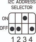
| Address Selection | ||||
|---|---|---|---|---|
| DIP 1 | DIP 2 | DIP 3 | DIP 4 | Address |
| ON | OFF | OFF | OFF | 0x49 |
| OFF | ON | OFF | OFF | 0x4B |
| OFF | OFF | ON | OFF | 0x4A |
| OFF | OFF | OFF | ON | 0x48 |
I2C Address Selection (Digital Inputs) #
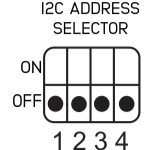
| Address Selection | ||||
|---|---|---|---|---|
| DIP 1 | DIP 2 | DIP 3 | DIP 4 | Address |
| OFF | OFF | 0x73 | ||
| ON | OFF | 0x72 | ||
| OFF | ON | 0x71 | ||
| ON | ON | 0x70 | ||
Wiring Guide #
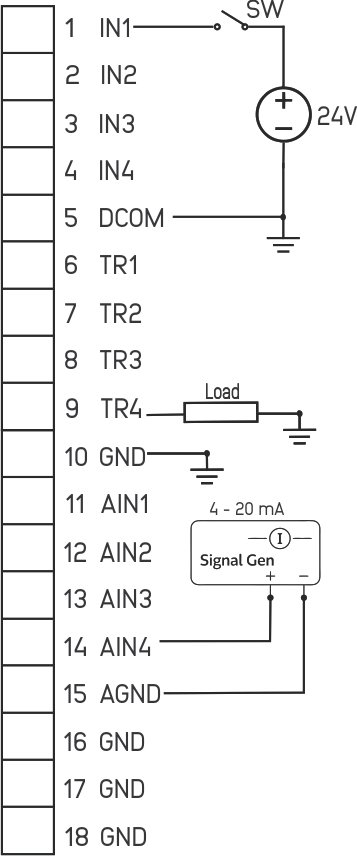
GPIO pin assignments for the I2C bus are listed in the Expansion Port table below. This section covers how to physically wire the module.
Power Connection #
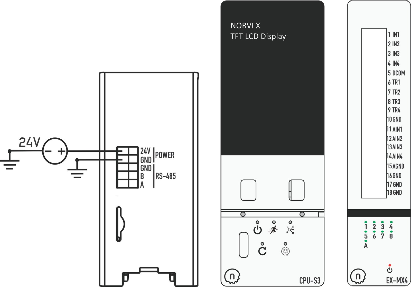
The module draws its 24 V DC supply through the expansion port, shared with the CPU, so no separate power terminal is wired on the NORVI X-MX4-CI.
Digital Input Wiring #
- For a sourcing (PNP) sensor, connect the sensor’s signal output to the corresponding INx terminal, and connect the sensor’s negative or ground lead to DCOM.
- For a sinking (NPN) sensor, connect the sensor’s signal output to the corresponding INx terminal, and tie the sensor’s positive lead to the 24 V supply, with DCOM referenced to the same supply ground.
- For a simple dry contact switch, wire one side of the contact to INx and the other side to DCOM.
- Since all four inputs share a single DCOM terminal, sourcing and sinking sensors cannot be mixed on the same module. Choose one wiring style for all four channels.
- The first four indicators (1–4) display the status of the digital input channels.
Transistor Output Wiring #
- The outputs are high-side switches: each TRx terminal switches the supply positive to the load, and the load returns to ground.
- Connect the load between the TRx terminal and GND.
- Keep each channel at or below 0.5 A. A channel that draws more than this will heat its PTC fuse, which trips at 1 A and resets once the fault is removed and the fuse cools.
- Fit a flyback diode across inductive loads such as relay coils and solenoids.
- Each transistor output channel has a dedicated LED indicator that illuminates when the channel is switched ON. Indicators 5–8 display the status of the transistor output channels.
Analog Input Wiring #
- Each of the four channels accepts a 4–20mA/0–20mA signal
- Connect the signal wire from your sensor or transmitter to the appropriate AINx terminal
- Connect the sensor’s signal return / negative lead to the AGND terminal
- Keep signal wiring away from AC/high-current runs
- Confirm the source stays within 0–20mA on every channel
- Set the DIP switch address and wire the required channels.
- Power on the system, then upload and run the test sketch.
Mounting and Connecting the Module #
- Power off the entire system before touching any wiring or seating the module.
- Mount the NORVI X-MX4-CI on the DIN rail next to the CPU module (or next to another expansion module already in the chain) and seat it firmly onto the expansion bus connector.
- Set the DIP switches to free I2C addresses for the analog and digital sections, especially if more than one module is being installed.
- Wire your field devices to the IN, TR, and AIN terminals, confirming each signal stays within the module’s ratings.
- Power the system back on.
- Upload the module’s test sketch from the NORVI GitHub repository to confirm each channel reads correctly before wiring it into your final control logic.
Expansion Port (50 pin) #
Utilized GPIO Connections are highlighted in Green. They cannot be used for any other purpose with this module connected.
| PIN INDEX | Purpose | GPIO | SOURCE |
|---|---|---|---|
| 1 | MOSI | IO11 | ESP32-S3 |
| 2 | MISO | IO13 | |
| 3 | SCLK | IO12 | |
| 4 | GND | —- | |
| 5 | SCL | IO9 | |
| 6 | SDA | IO8 | |
| 7 | GND | —- | |
| 8 | RX1 | IO18 | |
| 9 | TX1 | IO17 | |
| 10 | GND | —- | |
| 11 | D+ | —- | |
| 12 | D- | —- | |
| 13 | GND | —- | |
| 14 | CS1 | P1_0 | PCA9539 I2C Address 0x75 |
| 15 | CS2 | P0_7 | |
| 16 | CS3 | P0_6 | |
| 17 | CS4 | P0_5 | |
| 18 | IO1 | IO1 | ESP32-S3 |
| 19 | IO2 | IO2 | |
| 20 | IO4 | IO4 | |
| 21 | IO5 | IO5 | |
| 22 | IO6 | IO6 | |
| 23 | IO7 | IO7 | |
| 24 | IO10 | IO10 | |
| 25 | IO11 | IO35 | |
| 26 | IO12 | IO41 | |
| 27 | IO13 | IO37 | |
| 28 | IO14 | IO14 | |
| 29 | RS485_TX | IO15 | |
| 30 | GND | —- | |
| 31 | GND | —- | |
| 32 | RS485_RX | IO16 | |
| 33 | P1_1 | P1_1 | PCA9539 I2C Address 0x75 |
| 34 | P1_2 | P1_2 | |
| 35 | IO21 | IO21 | ESP32-S3 |
| 36 | GND | —- | |
| 37 | GND | —- | |
| 38 | P1_3 | P1_3 | PCA9539 I2C Address 0x75 |
| 39 | P1_4 | P1_4 | |
| 40 | P1_5 | P1_5 | |
| 41 | IO39 | IO39 | ESP32-S3 |
| 42 | IO40 | IO40 | |
| 43 | NC | —- | |
| 44 | NC | —- | |
| 45 | NC | —- | |
| 46 | GND | —- | |
| 47 | 5V | 5V | |
| 48 | GND | GND | |
| 49 | 24V | 24V | |
| 50 | 24V | 24V |
Software Setup (Arduino IDE) #
The NORVI X-MX4-CI is controlled through the host CPU using the Arduino IDE with the ESP32 board package. Firmware examples and required libraries are maintained in the NORVI GitHub repository.
Board Configuration #
- Install Arduino IDE
Install the Arduino IDE and add ESP32 board support:
Tools → Board → Boards Manager → ESP32 - Connect the Controller
Connect the NORVI X CPU to your computer using the USB interface. - Select Board and Port
Configure the board and communication port:- Tools → Board → ESP32 Arduino → ESP32S3 Dev Module
- Tools → Port → Select the corresponding COM/serial port
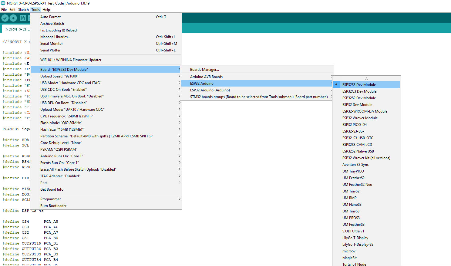
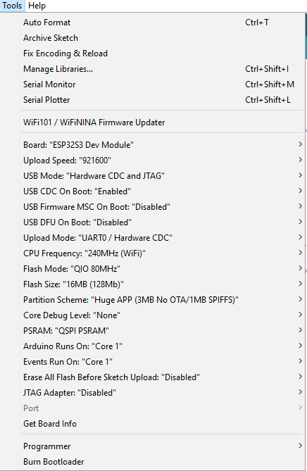
- Configure Board Settings
Under the Tools menu, configure the following settings:
| Setting | Selection |
|---|---|
| USB CDC On Boot | Enabled |
| Flash Size | 16MB (128Mb) |
| PSRAM | QSPI PSRAM |
Test Code Examples #
Required Libraries #
Install these via Arduino IDE → Sketch → Include Library → Manage Libraries before compiling any of the examples below:
- Wire
- SPI
- Adafruit_ADS1X15 (Adafruit ADS1X15, for the analog inputs)
- PCA9538 (I/O expander for the digital inputs and transistor outputs)
- LovyanGFX
Install the Required Library #
Install the Wire library through:
Sketch → Include Library → Manage Libraries
Search for Wire and install it if required.
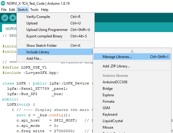
The Libraries are available in the NORVI-X-Version-02 GitHub repository.
Open and Upload the Test Sketch #
- Open the X-MX4-CI test sketch from the NORVI GitHub repository.
- Verify the board and port selections.
- Click Upload to upload the test sketch to the NORVI X CPU.
I2C Communication and Channel Reading #
Run an I2C scan first to confirm the module is detected before checking individual channels. With the default DIP settings you should see the analog converter at one of 0x48–0x4B and the digital section at one of 0x70–0x73.
#define SDA_PIN   8
#define SCL_PIN   9

Wire.begin(SDA_PIN, SCL_PIN);
Wire.setClock(400000);   // fast I2C

#define ADS_ADDR  0x4A

adsFound = ads1.begin(ADS_ADDR);

#define PCA9538_ADDR 0x71
#define PCA_RESET    21

pinMode(PCA_RESET, OUTPUT);
digitalWrite(PCA_RESET, HIGH);   // must be released before it responds

Wire.beginTransmission(PCA9538_ADDR);
pcaFound = (Wire.endTransmission() == 0);
Digital Input Test #
The four inputs are read through the PCA9538 expander at 0x71. The sketch releases the expander’s reset line (IO21), sets the input pins as inputs, and inverts each reading so an energised input shows as ACTIVE. Toggle each input and confirm its state changes on the display and the matching input LED follows.
#define PCA9538_ADDR 0x71
#define PCA_RESET    21

#define DI1_PIN 5
#define DI2_PIN 6
#define DI3_PIN 7
#define DI4_PIN 8

PCA9538 io(PCA9538_ADDR);

// in setup()
pinMode(PCA_RESET, OUTPUT);
digitalWrite(PCA_RESET, HIGH);   // release the expander reset
Wire.begin(SDA_PIN, SCL_PIN);

io.pinMode(DI1_PIN, INPUT);
io.pinMode(DI2_PIN, INPUT);
io.pinMode(DI3_PIN, INPUT);
io.pinMode(DI4_PIN, INPUT);

// in loop()
int in1 = !io.digitalRead(DI1_PIN);
int in2 = !io.digitalRead(DI2_PIN);
int in3 = !io.digitalRead(DI3_PIN);
int in4 = !io.digitalRead(DI4_PIN);
Transistor Output Test #
The sketch runs a walking test: one output is switched on at a time and moves to the next every second. Each output should switch on and off in turn, with its LED and the connected load following, and the display shows ON or OFF for DO1 to DO4.
#define DO1_PIN 1
#define DO2_PIN 2
#define DO3_PIN 3
#define DO4_PIN 4

const unsigned long OUT_STEP_MS = 1000;

// in setup(): outputs start OFF
io.pinMode(DO1_PIN, OUTPUT);
io.pinMode(DO2_PIN, OUTPUT);
io.pinMode(DO3_PIN, OUTPUT);
io.pinMode(DO4_PIN, OUTPUT);
io.digitalWrite(DO1_PIN, LOW);
io.digitalWrite(DO2_PIN, LOW);
io.digitalWrite(DO3_PIN, LOW);
io.digitalWrite(DO4_PIN, LOW);

// in loop(): one output ON at a time
if (millis() - lastOutSwitch >= OUT_STEP_MS) {
  lastOutSwitch = millis();
  for (int i = 0; i < 4; i++) {
    outState[i] = (i == activeOutput) ? HIGH : LOW;
  }
  io.digitalWrite(DO1_PIN, outState[0]);
  io.digitalWrite(DO2_PIN, outState[1]);
  io.digitalWrite(DO3_PIN, outState[2]);
  io.digitalWrite(DO4_PIN, outState[3]);
  activeOutput = (activeOutput + 1) % 4;
}
Analog Input Test #
The four analog inputs are read through the ADS1115 at 0x4A and shown in mA. Connect a 4–20 mA source or loop-powered sensor to AIN1 to AIN4 and confirm the readings track the signal.
#define ADS_ADDR 0x4A

Adafruit_ADS1115 ads1;
const float mA_Factor = 4.096 / 3269.826;

// in setup()
ads1.begin(ADS_ADDR);
ads1.setGain(GAIN_ONE);
ads1.setDataRate(RATE_ADS1115_860SPS);

// in loop()
float ch1 = ads1.readADC_SingleEnded(0) * mA_Factor;
float ch2 = ads1.readADC_SingleEnded(1) * mA_Factor;
float ch3 = ads1.readADC_SingleEnded(2) * mA_Factor;
float ch4 = ads1.readADC_SingleEnded(3) * mA_Factor;
Validating the Full Test Sketch #
When the complete sketch runs successfully, the display shows NORVI X-MX4-CI with live mA readings for CH1 to CH4, the ACTIVE or INACTIVE state of DI1 to DI4, and the ON or OFF state of DO1 to DO4. The serial monitor prints the same values once a second, plus an OK or NOT FOUND line for the ADS1115 and the PCA9538. Check each section against the connected field devices before integrating the module into your final control logic.
Troubleshooting #
| Symptom | Suggested Action |
|---|---|
| No response from a digital input | Check the wiring polarity and confirm DCOM is connected to the sensor’s return path. |
| Input LED stays off despite an active sensor | Confirm the input voltage exceeds the 15 V logic-high threshold. |
| Transistor output does not switch on | Confirm the load is wired between TRx and GND and that the 24 V supply is present on the expansion port. |
| Output switches off under load | The channel may have tripped its PTC fuse. Keep the load at or below 0.5 A, remove the fault, and let the fuse cool. |
| Analog reading is zero or fixed | Check loop wiring and polarity, confirm AGND is connected, and confirm the sensor is powered and outputting 4–20 mA. |
| ADS ERROR or PCA ERROR on the display, or NOT FOUND on the serial monitor | Power down, reseat the module on the expansion bus, and check that the DIP switch addresses do not conflict with another installed module. |
Explore technical files and available resources for this expansion module.
View on GitHub ↗Support & Resources #
REVISION HISTORY #
| Rev. | Date | Change Description | Board Revision |
|---|---|---|---|
| 1.0 | 04/11/2026 | Initial release | V1 |