
NORVI X is a next generation modular industrial controller designed to power smart automation and IoT solutions. Built around a CPU module and a range of plug and play expansion modules, the platform scales from a handful of I/O points up to 200, giving system integrators, OEMs, and industrial engineers a flexible foundation for automation, remote monitoring, and data acquisition projects.
The NORVI X-DI4 is a 4 channel digital input expansion module for the NORVI X range. Unlike most other digital input modules in the lineup, it wires its four inputs directly to the host CPU’s GPIO rather than through an I2C port expander. That direct connection is what lets it capture fast signals such as PWM, pulse trains, and encoder output, in addition to simple on and off sensing, while still supporting sourcing (PNP) sensor types.
Key Features #
- Four optically isolated 24 V DC digital inputs
- Direct GPIO connection to the host CPU for high speed signal acquisition
- Switching frequency up to 5 kHz in fast input mode
- Supports sourcing (NPN) input devices.
- One shared common terminal (DCOM) for all four inputs
- DIN rail mountable enclosure with spring terminals
- One status LED per input channel
- CE / EMC compliant (EN 61131-2:2007, EN 61010-1:2010+A1:2019, EN IEC 61010-2-201:2018, 2014/30/EU)
Safety Information #
Warning: Disconnect all power sources before installing, wiring, or servicing the NORVI X-DI4. Failure to do so may result in electric shock or damage to the equipment.
- Install and wire this module only if you are a qualified electrician or trained technician familiar with industrial control equipment.
- Confirm the host CPU is running from a regulated 24 V DC supply, since the module draws its power through the expansion port rather than a separate connection.
- Mount the module on a DIN rail inside a suitably rated enclosure. It carries an IP20 protection rating and is not designed for direct outdoor or wash down exposure.
- Keep the operating environment within minus 40 to plus 85 degrees C and avoid condensing humidity.
- Do not connect or disconnect the module from the expansion bus while the system is powered.
- Follow all local and national electrical codes applicable to industrial control panel wiring.
- The X-DI4 and X-UART-IO share the same GPIO pins (IO5, IO6, IO7, IO10) and cannot be used together in the same system. If your project needs both digital inputs and a UART interface, plan around this conflict rather than combining both modules. Check the NORVI X Mixing Guide before finalizing your module selection.
Technical Specifications #
Electrical #
| Rated Supply Voltage | 24V DC |
| Current Consumption | 40mA @ 24V DC |
Input Specifications #
| Number of Inputs | 4 digital Inputs |
| Input Type | Isolated 24 V DC, Sinking |
| Input Voltage Range | 0 to 30 V DC |
| Logic Low (OFF) | Below 5 V DC |
| Logic High (ON) | Above 15 V DC |
| Input Impedance | Approximately 3.3 kΩ |
| Input Current | Approximately 7 mA at 24 V DC |
| Switching Frequency | Up to 5 kHz in fast input mode |
| Isolation Type | Optocoupler per channel |
| Isolation Voltage | Above 1500 Vrms |
| Connector Type | Spring terminal |
Hardware Layout & GPIO Map #
The table below lists the GPIO pins reserved for the X-DI4’s four inputs on the host CPU. These pins are unavailable for any other use once the module is connected to the expansion bus.
| Terminal | Function | GPIO |
|---|---|---|
| IN1 | Digital Input 1 | IO5 |
| IN2 | Digital Input 2 | IO6 |
| IN3 | Digital Input 3 | IO7 |
| IN4 | Digital Input 4 | IO10 |
| DCOM | Isolated digital common | – |
Wiring Guide #
GPIO pin assignments for every input are listed in the Hardware Layout and GPIO Map section above; this section covers how to physically wire the module, not the pin numbers themselves.
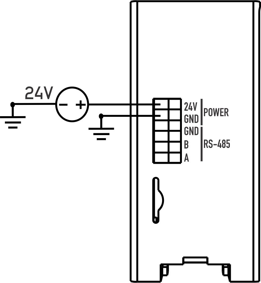
Power Connection #
The module draws its 24 V DC supply through the expansion port itself, shared with the CPU, so there is no separate power terminal to wire on the X-DI4.
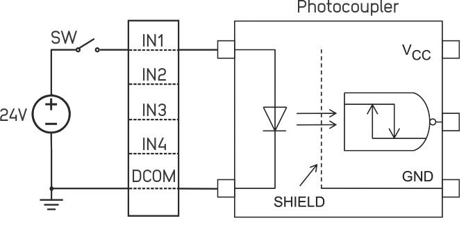
Digital Input Wiring #
- For a sourcing (PNP) sensor, connect the sensor’s signal output to the corresponding INx terminal, and connect the sensor’s negative or ground lead to DCOM.
- Since all four inputs share a single DCOM terminal, use the same wiring configuration for all four sourcing digital inputs.
Connecting the Module to the CPU #
- Power off the system.
- Mount the X-DI4 on the DIN rail next to the CPU module or an adjacent expansion module.
- Seat it firmly onto the expansion bus connector until it locks into place.
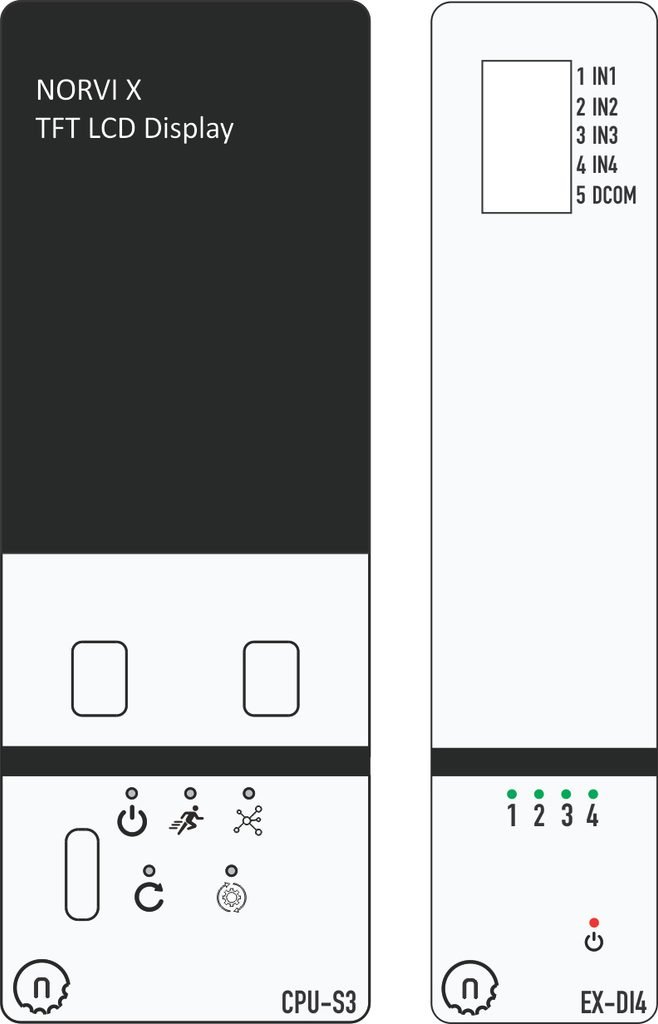
- Wire your field signals (switches, sensors, encoders) to the INPUT 1 through INPUT 4 terminals, confirming each signal stays within the module’s 0 to 30 V DC input range.
- Power the system back on.
- Upload the module’s test sketch from the NORVI GitHub repository to confirm each channel reads correctly before wiring it into your final control logic.
Expansion Port (50 pin) #
The X-DI4 connects via the same 50 pin expansion bus used across the NORVI X range. Pins 21 through 24 (IO5, IO6, IO7, IO10) are the ones this module claims; all others remain available for other expansion modules or custom wiring.
| PIN INDEX | Purpose | GPIO | SOURCE |
|---|---|---|---|
| 1 | MOSI | IO11 | ESP32-S3 |
| 2 | MISO | IO13 | |
| 3 | SCLK | IO12 | |
| 4 | GND | —- | |
| 5 | SCL | IO9 | |
| 6 | SDA | IO8 | |
| 7 | GND | —- | |
| 8 | RX1 | IO18 | |
| 9 | TX1 | IO17 | |
| 10 | GND | —- | |
| 11 | D+ | —- | |
| 12 | D- | —- | |
| 13 | GND | —- | |
| 14 | CS1 | P1_0 | PCA9539 I2C Address 0x75 |
| 15 | CS2 | P0_7 | |
| 16 | CS3 | P0_6 | |
| 17 | CS4 | P0_5 | |
| 18 | IO1 | IO1 | ESP32-S3 |
| 19 | IO2 | IO2 | |
| 20 | IO4 | IO4 | |
| 21 | IO5 | IO5 | |
| 22 | IO6 | IO6 | |
| 23 | IO7 | IO7 | |
| 24 | IO10 | IO10 | |
| 25 | IO11 | IO35 | |
| 26 | IO12 | IO36 | |
| 27 | IO13 | IO37 | |
| 28 | IO14 | IO14 | |
| 29 | RS485_TX | IO15 | |
| 30 | GND | —- | |
| 31 | GND | —- | |
| 32 | RS485_RX | IO16 | |
| 33 | P1_1 | P1_1 | PCA9539 I2C Address 0x75 |
| 34 | P1_2 | P1_2 | |
| 35 | IO21 | IO21 | ESP32-S3 |
| 36 | GND | —- | |
| 37 | GND | —- | |
| 38 | P1_3 | P1_3 | PCA9539 I2C Address 0x75 |
| 39 | P1_4 | P1_4 | |
| 40 | P1_5 | P1_5 | |
| 41 | IO39 | IO39 | ESP32-S3 |
| 42 | IO40 | IO40 | |
| 43 | NC | —- | |
| 44 | NC | —- | |
| 45 | NC | —- | |
| 46 | GND | —- | |
| 47 | 5V | 5V | |
| 48 | GND | GND | |
| 49 | 24V | 24V | |
| 50 | 24V | 24V |
Software Setup (Arduino IDE) #
The NORVI X-DI4 is read through the host CPU using the Arduino IDE with the ESP32 board package. Firmware examples and required libraries are maintained in the NORVI GitHub repository.
Board Configuration #
Install Arduino IDE #
Install the Arduino IDE and add ESP32 board support:
Connect the Controller #
Connect the NORVI X CPU to your computer using the USB interface.
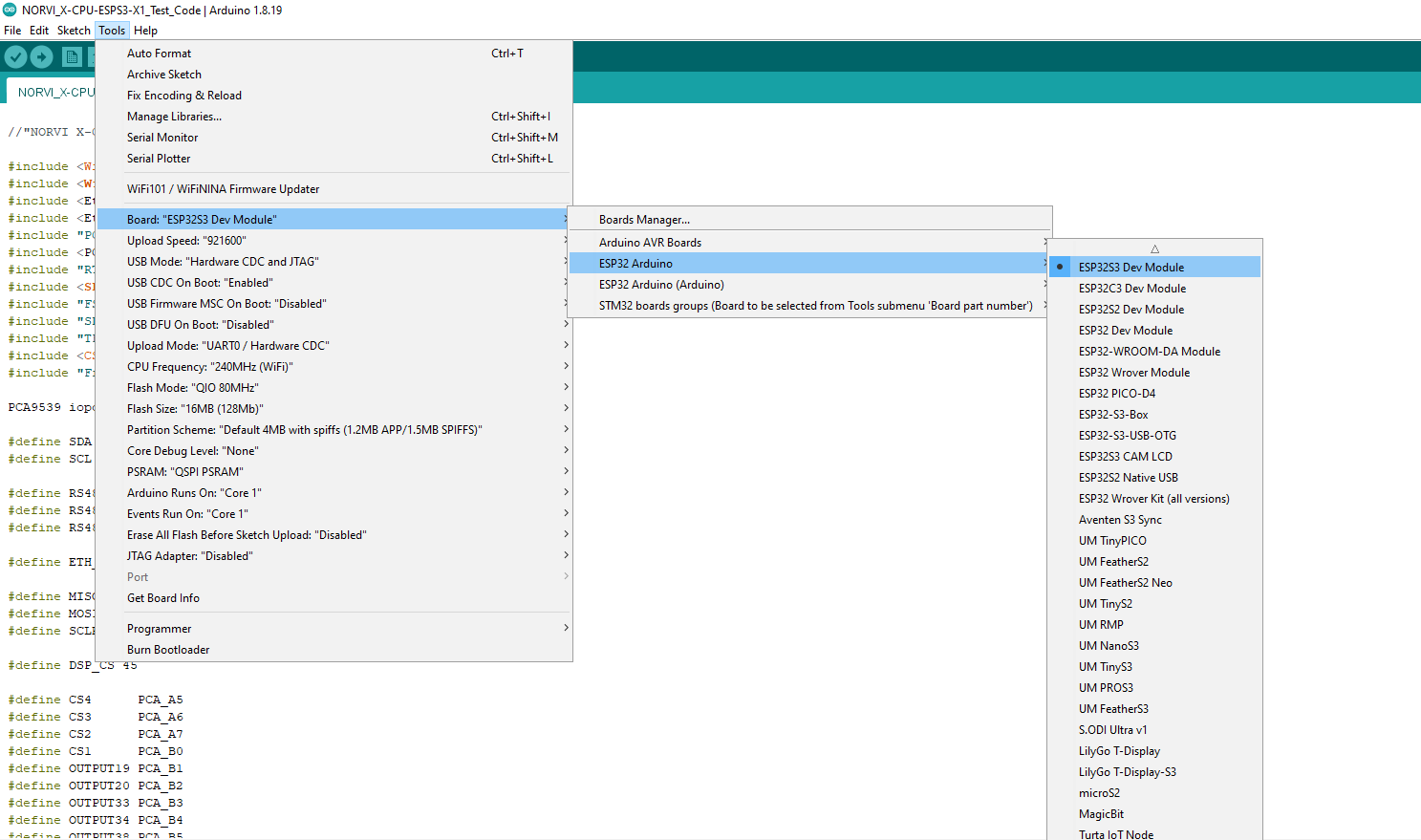
Configure Board Settings #
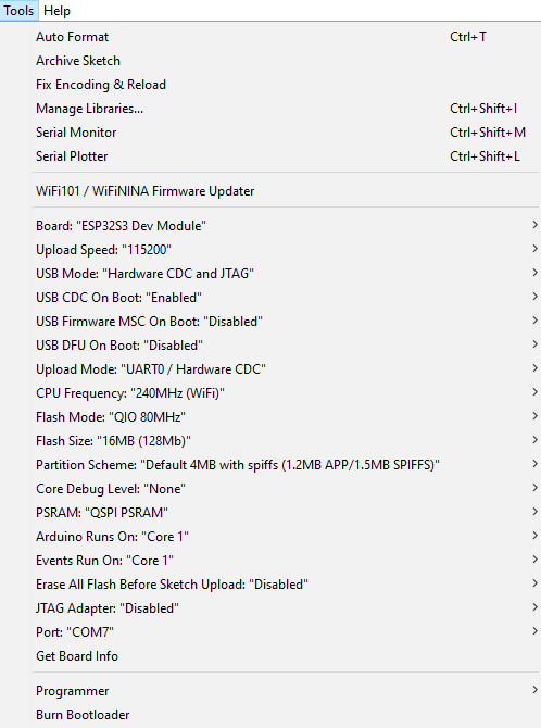
Under the Tools menu, configure the following settings:
| Setting | Selection |
|---|---|
| USB CDC On Boot | Enabled |
| Flash Size | 16MB (128Mb) |
| PSRAM | QSPI PSRAM |
Test Code Examples #
Required Libraries #
Install these via Arduino IDE → Sketch → Include Library → Manage Libraries before compiling any of the examples below:
WireWiFiEthernetSPIPCA9539PCA9536DRTClib (DS3231 RTC)TFT_eSPICST816S
ESP32 pulse counter tutorial
Install the Required Library #
Install the Wire library through:
Sketch → Include Library → Manage Libraries
Search for Wire and install it if required.
The Libraries are available in the NORVI-X-Version-02 GitHub repository.
Open and Upload the Test Sketch #
- Open the X-DI4 test sketch from the NORVI GitHub repository.
- Verify the board and port selections.
- Click Upload to upload the test sketch to the NORVI X CPU.
Digital Input Read (X-DI4 Test Sketch Excerpt) #
The following excerpt reads all four X-DI4 channels and prints any state change to the Serial Monitor. It’s taken from the module’s test sketch in the NORVI-X-Version-02 GitHub repository, under the expansion modules folder.
#define INPUT1 5
#define INPUT2 6
#define INPUT3 7
#define INPUT4 10

pinMode(INPUT1, INPUT);
pinMode(INPUT2, INPUT);
pinMode(INPUT3, INPUT);
pinMode(INPUT4, INPUT);

tft.print(digitalRead(INPUT1));
tft.print(digitalRead(INPUT2));
tft.print(digitalRead(INPUT3));
tft.print(digitalRead(INPUT4));
When the module is wired correctly, toggling a sensor or dry contact on any of the four inputs should print an immediate state change on the Serial Monitor, and the corresponding LED on the module should light up while the input is active.
For a practical application, follow our ESP32 pulse counter tutorial to measure flow-meter pulses and count production parts using NORVI X-DI4 fast inputs.
Validating the Full Test Sketch #
When the module is wired correctly, the display shows INPUT 1 through INPUT 4 with a live value next to each. Toggling a sensor or dry contact on any channel should flip its value between 0 and 1 on screen within about half a second, confirming that channel is reading correctly before it goes into your final control logic.
Troubleshooting #
| Symptom | Suggested Action |
|---|---|
| No response from an input | Check the wiring polarity and confirm that DCOM is properly connected to the sensor’s return path. |
| LED stays off despite an active sensor | Confirm that the input voltage exceeds the 15 V logic-high threshold. |
| Inconsistent readings on fast signals | Confirm that the source frequency remains within the 5 kHz switching limit. |
| Module not detected by the CPU | Power down, reseat the module on the expansion bus, and confirm that no other module is already using IO5, IO6, IO7, or IO10. |
| TFT display blank or not working | Check three settings under Tools: USB CDC On Boot set to Enabled, Flash Size set to 16MB (128Mb), and PSRAM set to QSPI PSRAM. |
10. Support & Resources #
Access product documentation, firmware resources, and technical support for your NORVI device.