
Power Source Selection #
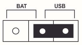
The device has a built-in battery, which is designed for low power operation. During programming and testing of the device, the power source can be changed to USB to save the battery power for its actual operation. The power source can be changed to USB by setting the on board Jumper to position 2.
Battery Monitoring #
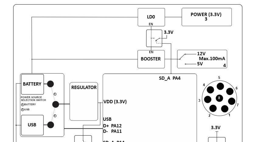
The system utilizes a dual-input architecture where a selection switch directs Battery power (position ①) through a Regulator to establish the main VDD (3.3V) system rail. The raw battery line also directly feeds an LDO and a Booster circuit, allowing the system to step up voltages up to 12V (Max. 100mA) or 5V. Power delivery to these booster stages is managed dynamically by the microcontroller using the SD_A PA4 control pin to toggle the enable (EN) lines.
Programming the Device #
NORVI EC-M12-BC-C6-C-B is powered by a STM32L Series microcontroller, STM32L072CZT6. This microcontroller is designed for low power applications and can be programmed with Arduino IDE or any other IDE which supports STM32 micro-controllers.
The board includes SWD programming Pins for connection with an ST-Link and USB Port for Serial Debugging.
Configuring Arduino IDE for STM32L
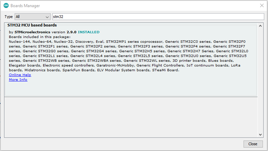
The boards package : STM32 MCU Based boards should be installed from the Arduino Boards Manager.
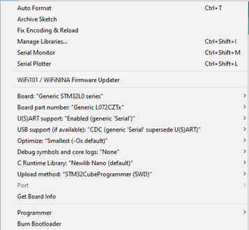
Then setup the board setting from tools as the below Figure. In there; to get the serial monitor output needed to enable generic serial and CDC (generic ‘serial’ superseded U(S)ART.
Board : Generic STM32L0 Series
Board Part number : Generic L072CZTx
U(S)ART support : Enabled generic Serial
Compiling and Uploading Code for STM32L with Arduino IDE #
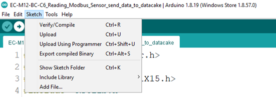
The compiled binary can be downloaded from Arduino IDE from Sketch –> Export Compiled Binary Option.
Once the process is complete the binary file can be fetched from the program’s saved location.
The exported binary file can be uploaded through a ST-Link Programmer.
The connections GROUND, CLK, DIO, RESET should be connected with the ST-Link Programme.
RS-485 Communication #
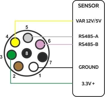
RS-485 Communication is handled by SN65HVD72DGKR RS-485 transceiver. MODBUS RTU Protocol or any other RS-485 based protocols can be established with the transceiver.
| Driver | SN65HVD72DGKR |
| UART RX | PB7 |
| UART TX | PB6 |
| Flow Control | PB5 |
RS-485 Wiring #
Programming RS-485 #
The example code below initialized the UART Module for RS-485 transceiver and sends the message “RS485 01 SUCCESS” over RS-485 bus. After that the module is set to receiving mode to receive messages.
// ================= RS485 =================
#define RS485_RX PB7
#define RS485_TX PB6
#define FC       PB5   // DE + RE pin


 // ================= RS485 TRANSMIT =================
  digitalWrite(FC, HIGH);     // TX mode
  delay(5);


  Serial1.println("RS485 01 SUCCESS");
  Serial1.flush();            // IMPORTANT


  delay(5);
  digitalWrite(FC, LOW);      // RX mode


  // ================= RS485 RECEIVE =================
  unsigned long startTime = millis();
  while (millis() - startTime < 200) {
    if (Serial1.available()) {
      char c = Serial1.read();
      Serial.write(c);
    }
Sensor Supply Voltage Output #
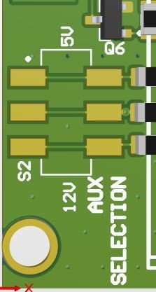
The EC-M12-BC-C6 Series includes a software-controlled auxiliary power output for powering external sensors and devices. The output can be enabled or disabled by the application to reduce power consumption and provide up to 200 mA of output current. The output voltage can be selected as 5V or 12V using the onboard AUX Selection jumper.
The output voltage can be selected between 5V or 12V.
Enabling Power Output from firmware
The output enable pin is connected to the GPIO PA4 on STM32. By turning the PA4 High,
the output can be turned ON.
The program below performs output being turned ON and OFF every 1 second.
#define BOOST_EN PA4


// ---------- GPIO ----------
  pinMode(BOOST_EN, OUTPUT);
  pinMode(GSM_POWER, OUTPUT);
  pinMode(FC, OUTPUT);


  digitalWrite(BOOST_EN, HIGH);
  digitalWrite(FC, LOW);          // RS485 default RX mode


  // ---------- SERIAL ----------
  Serial1.begin(9600);            // RS485
  delay(100);
  Serial2.begin(9600);            // GSM
  delay(100);
MicroSD Card Support #
The microSD card is connected to the SPI Bus of the STM32 with a GPIO to control power to the microSD Card. This is implemented to cut off power to the microSD Card when the device is in sleep mode. Below example code shows, to enable power to the microSD Card and read the data.
// ================= SPI =================
#define MISO_PIN PA6
#define MOSI_PIN PA7
#define SCLK_PIN PA5
// ================= SD =================
#define SD_chipSelect PB0
Sd2Card card;
SdVolume volume;
SdFile root;


void SD_CHECK() {


  Serial.print("\nInitializing SD card...");
  if (!card.init(SPI_HALF_SPEED, SD_chipSelect)) {
    Serial.println("CARD NOT FOUND");
    return;
  }


  Serial.println("SD WORKING");
  Serial.print("Card type: ");
  Serial.println(card.type());


  if (!volume.init(card)) {
    Serial.println("FAT16/FAT32 NOT FOUND");
    return;
  }


  if (!SD.begin(SD_chipSelect)) {
    Serial.println("SD BEGIN FAILED");
    return;
  }
  Serial.println("SD READY");
}
Low Power Mode #
Preparing for Low Power #
Before entering sleep, all peripherals are powered down in a defined sequence:
| Step | Action | Purpose |
|---|---|---|
| 1 | SPI.end() | Stop SD communication |
| 2 | Wire2.end() | Disable I²C bus |
| 3 | digitalWrite(FC, LOW) | Disable flow control / put RS-485 in receive mode |
| 4 | digitalWrite(SD_PWR, LOW) | Power off SD card |
| 5 | digitalWrite(BOOST_EN, LOW) | Disable booster and INA196 |
| 6 | digitalWrite(GSM_POWER, HIGH) | Turn off GSM module |
| 7 | Delay 2 s | Ensure all subsystems shut down safely |
Entering Low Power Mode #
After peripherals are powered down:
LowPower.shutdown(ShutdownPeriod);
This command puts the STM32 into deep-shutdown mode for the defined duration (here ShutdownPeriod = 30000 ms, i.e. 30 s).
In shutdown mode:
- Most peripherals and clocks are off.
- Power consumption drops to a few microamps.
- The RTC keeps running and wakes the MCU automatically when the timer expires.
Wake-Up and Resume
After the shutdown period ends:
- The MCU restarts from setup() (a cold start).
- Peripherals are re-initialized.
- Normal data acquisition and communication resume.
- The cycle repeats.
Notes
To change sleep duration, edit:
uint32_t ShutdownPeriod = ;
Avoid serial communication immediately before shutdown to prevent incomplete transmissions.
Modem NB-IoT / 2G #
| Model of GSM Modem | SIMCOM SIM7070G |
| Bands Supported | Cat-M1: B1 / B2 / B3 / B4 / B5 / B8 / B12 / B13 / B14 / B18 / B19 / B20 / B25 / B26 / B27 / B28 / B66 / B85. Cat-NB (NB1/NB2): B1 / B2 / B3 / B4 / B5 / B8 / B12 / B13 / B18 / B19 / B20 / B25 / B26 / B28 / B66 / B71 / B85. 2G (GSM/GPRS/EDGE): 850 / 900 / 1800 / 1900 MHz (quad-band). |
| Technology | 4G LPWA: LTE Cat-M1 (eMTC) and LTE Cat-NB (NB1/NB2). 2G fallback: GPRS/EDGE (quad-band) |
| RXD | PA3 |
| TXD | PA2 |
| POWER | PA1 |
| DTR | PB12 |
The GSM modem on the EC-M12-BC-C6-C-B is connected to the microcontroller via Serial2 (PA2 – TX, PA3 – RX).
It can be accessed directly using standard AT commands for basic communication and testing.
After powering on the modem (digitalWrite(GSM_POWER, LOW)), open the serial interface at 9600 bps and send AT commands such as:
Serial2.println(“AT”);
The modem will respond with “OK” if communication is successful.
Note: This section covers only basic AT command communication and testing.
Refer to the “Using the Modem for Different Types of Connections” guide for details on data, SMS, and network configurations.
Indicator LED #
The device includes an Indicator LED connected to the NET light output of the GSM modem. This LED reflects the modem’s network status as follows:
- Blinking every 1 second: Modem is searching for a network.
- Blinking every 3 seconds: Modem is registered on the network successfully.
- Blinking rapidly: Modem is establishing a data connection.
- Off: Modem is powered off or in low-power mode.
The Indicator provides a quick visual reference to confirm modem activity and network connection status.