Key Takeaways:
- Every 8°C temperature increase cuts transformer insulation life in half
- NORVI’s modular system scales from 4 to 200+ I/O points
- Built-in Wi-Fi, Ethernet, and RS-485 enable seamless integration
- Professional-grade monitoring at 40-60% lower cost than traditional systems
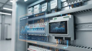
Power transformers quietly power our modern world, converting voltages to deliver electricity to homes, hospitals, and industries. Yet excessive heat remains their biggest enemy, causing premature failures and costly downtime. For utilities and facility managers, implementing effective temperature monitoring isn’t optional anymore – it’s essential for protecting these critical assets.
The NORVI industrial controller platform offers a practical solution. With modular analog inputs and comprehensive connectivity, it transforms complex transformer monitoring into an accessible, cost-effective system that scales with your needs.
Why Temperature Monitoring Saves Transformers
Transformer lifespan depends directly on temperature. According to IEEE standards, winding insulation deteriorates exponentially with heat. The “8°C rule” is sobering: exceeding rated temperature by just 8°C can cut a transformer’s expected life in half. A 30-year-rated transformer could fail in 15.
Typical limits:
- Oil-immersed transformers: 65°C average winding rise
- Dry-type transformers: 80–150°C depending on insulation class
Continuous monitoring delivers:
- Asset Protection: Detect early thermal issues before insulation or oil degrades.
- Optimized Loading: Safely utilize transformers at peak demand.
- Predictive Maintenance: Track trends to schedule repairs during planned outages.
- Compliance Documentation: Automated logging satisfies grid code requirements.
Critical Measurement Points
For effective industrial transformer monitoring, measure three key points:
- Top Oil Temperature – Indicates overall thermal loading and cooling performance. Early warning of clogged radiators, failed fans, or circulation issues.
- Winding Hot Spot Temperature – Highest stress point inside windings, directly influencing insulation life. NORVI supports direct measurement or calculated estimates.
- Ambient Temperature – Contextual data ensures accurate load corrections and distinguishes real faults from normal environmental variations.
The NORVI Advantage for Temperature Monitoring
NORVI X represents next-generation industrial control designed specifically for modular IoT applications. Its architecture addresses the exact challenges utilities and industrial facilities face when implementing transformer monitoring.
Hardware That Scales
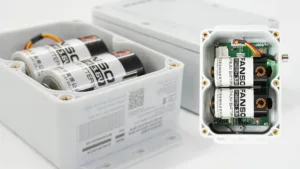
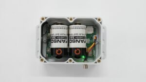
The NORVI X CPU-ESPS3-X1 packs serious capability into a compact DIN-rail package. The ESP32-S3 processor with 16MB flash and 2MB PSRAM handles complex calculations and data logging effortlessly. Built-in Wi-Fi, Bluetooth, Ethernet, and RS-485 ensure you can connect to any existing infrastructure.
The 2.0-inch TFT touchscreen provides local visualization without separate HMI equipment. Operating from 24V DC power, the entire controller draws just 400mA – negligible compared to the assets you’re protecting.
What makes NORVI different:
- True modularity: start with 4 inputs, expand to 200+
- Mix and match analog/digital I/O as needed
- Industrial certifications (EN 61131-2, EN 61010)
- -10°C to +85°C operating range
- Open programming (Arduino IDE compatible)
Analog Input Options
NORVI expansion modules suit all transformer monitoring needs:
- 0–10V modules: Work with voltage-output transmitters, ideal for short runs (<100m)
- 4–20mA modules: Industry standard, excellent for long runs (up to 1,000m), noise-resistant
- Thermocouple modules: Direct Type K, J, T connections for extreme temperature ranges
Modules communicate via SPI/I2C addressing mount, connect, and configure easily.
Implementation: From Sensors to Software
Building a working monitoring system involves three key steps: sensor selection, proper installation, and intelligent programming.
Choosing Temperature Sensors
Pt100 RTDs with 4-20mA transmitters represent the sweet spot for most installations. Excellent accuracy, linear response, and compatibility with long cable runs make them the industrial standard. The 4-20mA output works perfectly with NORVI’s current input modules.
Thermocouples offer wider temperature ranges and lower sensor cost but require more careful installation and calibration. They work well for applications where extreme temperatures or very fast response matters more than absolute accuracy.
Direct RTD connection is possible using specialized modules, though most installations benefit from transmitters that convert resistance to current signals. Transmitters also provide local display and configuration options.
Wiring for Accuracy
Proper installation ensures reliable measurements. Run sensor cables separately from power wiring—minimum 300mm separation prevents interference. Use shielded twisted-pair for all analog signals, grounding shields at the controller end only to avoid ground loops.
NORVI’s push-in terminals simplify connections, but verify wire gauge compatibility. Loose connections cause intermittent readings that mask real problems or trigger false alarms.
Installation checklist:
- Mount controller in clean, ventilated panel
- Separate signal and power cables appropriately
- Use shielded cable for all analog inputs
- Ground shields at one end only
- Label every connection clearly
- Document sensor locations and types
Programming Essentials
NORVI’s Arduino IDE compatibility makes programming accessible. Reading analog inputs starts with ESP32-S3 ADC functions, converting raw values to temperature using sensor-specific scaling.
For 4-20mA sensors: Temperature = ((Current – 4mA) / 16mA) × Range + Offset
Implement moving average filters to smooth electrical noise. Averaging 10-20 samples per second produces stable readings updated every second.
Alarm logic needs two levels:
- High Alarm (85-95°C): warns operators, sends notifications
- High-High Alarm (>95°C): triggers trips, demands immediate action
Include time delays (30-60 seconds) to prevent nuisance alarms from brief transients. Differentiate between normal load-related temperature rises and genuine fault conditions.
Sample code to read tempter data and set alarm triggers send notifications:
#include <Wire.h>
#include <WiFi.h>
#include <SPI.h>
#include <ModbusMaster.h>
#include "TFT_eSPI.h"
#include <CST816S.h>
#include "Free_Fonts.h"

// -------------------- I2C Pins --------------------
#define SDA   8
#define SCL   9

// -------------------- RS485 Pins --------------------
#define RS485_RXD 16
#define RS485_TXD 15
#define RS485_FC  41

// -------------------- SPI Pins --------------------
#define MISO 37
#define MOSI 35
#define SCLK 36

// -------------------- Alarm / Buzzer Pins --------------------
#define QF1 14  // Buzzer

// -------------------- Touch --------------------
CST816S touch(SDA, SCL, 47, 48);  // SDA, SCL, RESET, IRQ

// -------------------- TFT Display --------------------
TFT_eSPI tft = TFT_eSPI();

// -------------------- Modbus --------------------
ModbusMaster node;

// -------------------- Acknowledge Variables --------------------
bool alarmAcknowledged = false;
unsigned long ackTime = 0;
const unsigned long ackDuration = 30000; // 30 seconds silence

// -------------------- Functions --------------------
void preTransmission() { digitalWrite(RS485_FC, HIGH); }
void postTransmission() { digitalWrite(RS485_FC, LOW); }

// -------------------- Setup --------------------
void setup() {
  Serial.begin(115200);
  delay(2000);

  Serial.println("NORVI X Temperature Monitoring");

  pinMode(QF1, OUTPUT);
  digitalWrite(RS485_FC, LOW);

  Wire.begin(SDA, SCL);
  SPI.begin(SCLK, MISO, MOSI);

  Serial1.begin(115200, SERIAL_8N1, RS485_RXD, RS485_TXD);
  node.begin(1, Serial1);
  node.preTransmission(preTransmission);
  node.postTransmission(postTransmission);

  tft.init();
  tft.begin();
  tft.setRotation(0);
  tft.fillScreen(TFT_BLACK);
  tft.setTextColor(TFT_YELLOW);
  tft.setFreeFont(FSB12);
}

// -------------------- Display --------------------
void displayData(float temperature, float humidity, int alarmLevel) {
  tft.fillScreen(TFT_BLACK);

  tft.setCursor(60, 20);
  tft.setTextColor(TFT_YELLOW); tft.print("NORVI");

  tft.setCursor(20, 40);
  tft.setTextColor(TFT_YELLOW); tft.print("CONTROLLERS");

  tft.setCursor(10, 80);
  // Temperature color coding
  if(alarmLevel == 0) tft.setTextColor(TFT_YELLOW);
  else if(alarmLevel == 1) tft.setTextColor(TFT_ORANGE);
  else if(alarmLevel == 2) tft.setTextColor(TFT_ORANGE);
  else if(alarmLevel == 3) tft.setTextColor(TFT_RED);
  else tft.setTextColor(TFT_MAGENTA);

  tft.print("Temperature: "); tft.println(temperature);

  tft.setCursor(10, 100);
  tft.setTextColor(TFT_YELLOW);
  tft.print("Humidity: "); tft.println(humidity);

  tft.setCursor(10, 120);
  tft.setTextColor(TFT_YELLOW);
  tft.print("Alarm: ");
  switch(alarmLevel) {
    case 0: tft.println("NORMAL"); break;
    case 1: tft.println("WARNING"); break;
    case 2: tft.println("CRITICAL"); break;
    case 3: tft.println("HIGH"); break;
    case 4: tft.println("HIGH-HIGH"); break;
  }

  // Draw Acknowledge Button
  int btnX = 50, btnY = 150, btnW = 200, btnH = 40;
  if(alarmAcknowledged) tft.fillRect(btnX, btnY, btnW, btnH, TFT_GREEN);
  else tft.fillRect(btnX, btnY, btnW, btnH, TFT_RED);
  tft.setTextColor(TFT_WHITE);
  tft.setCursor(btnX + 20, btnY + 10);
  tft.print("Acknowledge Alarm");
}

// -------------------- Buzzer --------------------
void buzzerWarning(int alarmLevel) {
  // If acknowledged and within silence duration, do not beep
  if(alarmAcknowledged && millis() - ackTime < ackDuration) {
    digitalWrite(QF1, LOW);
    return;
  } else if(alarmAcknowledged) {
    alarmAcknowledged = false; // Reset acknowledge after duration
  }

  switch(alarmLevel) {
    case 0: digitalWrite(QF1, LOW); break;
    case 1: digitalWrite(QF1, HIGH); delay(300); digitalWrite(QF1, LOW); delay(700); break;
    case 2: digitalWrite(QF1, HIGH); delay(150); digitalWrite(QF1, LOW); delay(150); break;
    case 3: digitalWrite(QF1, HIGH); delay(100); digitalWrite(QF1, LOW); delay(100);
            Serial.println("**HIGH ALARM: Notify operators!**"); break;
    case 4: digitalWrite(QF1, HIGH); delay(500); digitalWrite(QF1, LOW); delay(100);
            Serial.println("**HIGH-HIGH ALARM: Immediate action required!**"); break;
  }
}

// -------------------- Touch Check --------------------
void checkTouch() {
  if(touch.touched()) {
    touch.read();
    int tx = touch.getX();
    int ty = touch.getY();
    // Button coordinates
    if(tx >= 50 && tx <= 250 && ty >= 150 && ty <= 190) {
      alarmAcknowledged = true;
      ackTime = millis();
      Serial.println("Alarm acknowledged! Buzzer silenced for 30 seconds.");
    }
  }
}

// -------------------- Main Loop --------------------
void loop() {
  float temperature = NAN;
  float humidity = NAN;
  int alarmLevel = 0;

  // -------------------- Read Modbus --------------------
  uint8_t result = node.readInputRegisters(0x0001, 2);
  if (result == node.ku8MBSuccess) {
    int16_t tempRaw = (int16_t)node.getResponseBuffer(0);
    uint16_t humRaw = node.getResponseBuffer(1);
    temperature = tempRaw / 10.0;
    humidity    = humRaw / 10.0;

    Serial.print("Temperature: "); Serial.println(temperature);
    Serial.print("Humidity: "); Serial.println(humidity);
  } else {
    Serial.println("Modbus read failed");
    Serial.println(result, HEX);
  }

  // -------------------- Determine Alarm Level --------------------
  if(temperature >= 95.0) alarmLevel = 4;
  else if(temperature >= 85.0) alarmLevel = 3;
  else if(temperature >= 80.0) alarmLevel = 2;
  else if(temperature >= 75.0) alarmLevel = 1;
  else alarmLevel = 0;

  // -------------------- Buzzer --------------------
  buzzerWarning(alarmLevel);

  // -------------------- Touch Button --------------------
  checkTouch();

  // -------------------- Display --------------------
  displayData(temperature, humidity, alarmLevel);

  delay(500);
}
Real-World Applications
Distribution Transformer Monitoring
Municipal utilities protect critical-load transformers serving hospitals and data centers with single-controller installations. One NORVI CPU with a 4-channel analog module monitors top oil, winding, and ambient temperatures. Cellular expansion modules provide remote access without requiring network infrastructure.
The system displays locally while transmitting data to central operations. When temperatures climb, operators receive alerts with time to respond – reducing load, dispatching maintenance, or switching to backup transformers.
Substation Integration
Large substations benefit from NORVI’s scalability. A central controller with multiple analog modules monitors 16+ points across several transformers. Ethernet connectivity integrates with existing SCADA through Modbus TCP or IEC 61850 protocols.
The NORVI system preprocesses data locally, executing immediate protection logic while reporting to station automation. This distributed intelligence improves reliability – local protection continues even if communication fails.
Industrial Power Systems
Manufacturing facilities can’t afford transformer failures. Production interruptions cost far more than equipment replacement. NORVI monitoring integrates into plant DCS networks, giving operators transformer health visibility alongside process parameters.
Modular architecture enables phased deployment. Start with the most critical transformers, expanding coverage as budget allows. Each installation delivers ROI through prevented outages and extended equipment life.
Advanced Features Worth Implementing
Thermal modeling calculates winding hot spot temperature using IEEE C57.91 algorithms. NORVI’s processor handles these calculations in real-time, providing accurate estimates without expensive fiber optic sensors.
Automated cooling control stages fans and pumps based on actual thermal conditions. Smart activation prevents unnecessary equipment cycling while ensuring adequate cooling capacity when needed.
Loss-of-life calculations track accumulated insulation aging, supporting data-driven replacement planning. Integration with enterprise asset management systems enables condition-based maintenance scheduling.
Maintenance and Troubleshooting
Annual calibration verification keeps systems accurate. Compare measured values against calibrated references, documenting results for regulatory compliance. Sensors showing drift beyond ±2°C require recalibration or replacement.
Common issues and fixes:
- Erratic readings: Improve cable shielding, separate from power conductors
- Communication failures: Check network settings, cable connections, firewall rules
- Sensor faults: Test continuity, verify resistance values, check transmitter power
- Incorrect values: Recalibrate scaling factors, verify sensor specifications
Regular firmware updates maintain security and add features. NORVI supports over-the-air updates via WiFi, simplifying deployment across multiple sites.
Conclusion: Protection That Pays
Transformer temperature monitoring with NORVI delivers professional capability at practical costs. The modular platform scales from simple single-transformer installations to complex multi-asset systems monitoring dozens of points.
Built-in connectivity ensures integration with existing infrastructure while supporting modern IoT architectures. Arduino IDE compatibility accelerates development for engineers familiar with microcontroller programming.
For utilities, industrial facilities, and anyone protecting valuable transformer assets, NORVI provides the foundation for effective monitoring that extends equipment life and prevents costly failures.
Whether protecting one critical distribution transformer or monitoring an entire fleet, NORVI offers the flexibility to implement exactly what you need – starting small and expanding as requirements evolve.
Ready to Implement?