

The EC-M12-BC-C6-C-D is a rugged, IP67-rated IoT telemetry unit designed for reliable outdoor and remote monitoring applications. Powered by high-capacity non-rechargeable lithium batteries, it delivers years of autonomous operation even in harsh environments.
Built on the ultra-low-power STM32L072CZT6 MCU, the device supports multi-network cellular connectivity for seamless data transmission. It also integrates directly with 2 × Analog Inputs (4–20 mA) and Digital Input interfaces, making it ideal for utilities, environmental monitoring, agriculture, and industrial asset management.
- Rugged Outdoor Design
- IP67 weatherproof enclosure for reliable operation in rain, dust, and extreme outdoor environments
- Industrial-grade connectors with cable gland for secure field deployment
- Cellular Connectivity
- Multi-band modem: 2G / Cat-M / Cat-NB (NB-IoT)
- Available with SIM7070 module for wide coverage and low-power IoT data transfer
- Power Supply
- Two ER34615H lithium batteries (19,000 mAh each)
- Total capacity: 38,000 mAh
- Non-rechargeable, optimized for multi-year, maintenance-free operation
- System Functions
- Built-in Reset Button
- Battery Isolation Switch (supports operation on USB power only)
- microSD storage expansion
- Accessories
- Industrial cable gland connector for sealed field wiring
Applications #
- Smart agriculture (soil moisture & irrigation monitoring)
- Environmental monitoring (air & water quality)
- Utility metering (water, gas, energy)
- Industrial equipment monitoring
- Tank level & fuel monitoring
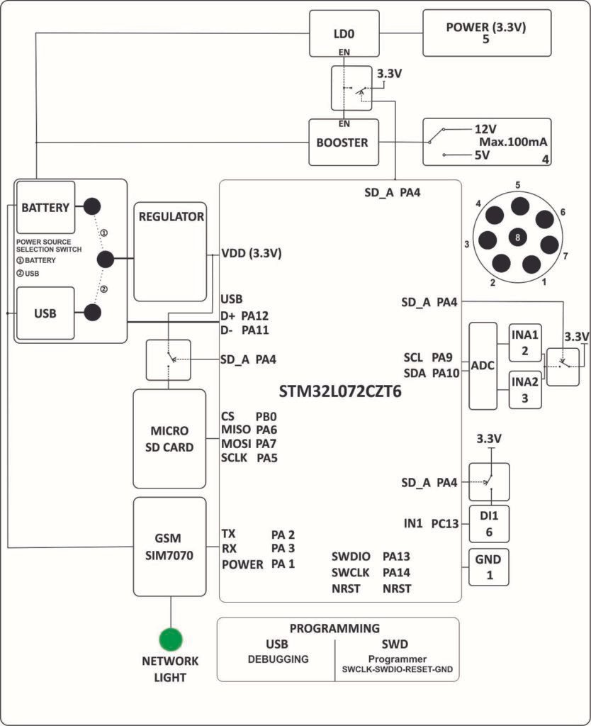
Product Block Diagram #
Technical Specifications #
Main #
| Range of Product | NORVI SENSOR NODE |
| Product Type | Programmable Sensor Node |
| Certifications | EN 61131-2:2007 EN 61010-1:2010+A1:2019 EN IEC 61010-2-201:2018 2014/30/EU- Electromagnetic Compatibility (EMC) Annex III, Part B, Module C |
| Rated supply voltage | Built-in Battery LiSoCL |
| Communication | SIMCOM SIM7070 – 2G / NB-IoT |
| Inputs | 1 x Digital Input 2 x Analog Input |
| Sensor Power | 12V DC / 5V DC |
| Displays and Visual Indicators | Connectivity Indicator |
Complementary #
| Product Unified Code | EC-M12-BC-C6-C-D |
| Product Part Numbers | EC-M12-BC-C6-C-D |
Mechanical Properties #
| Enclosure | ABS + PolyCarbonate / IP67 |
| Mounting / Installation Method | Wall mount / Pole Mount |
| Terminal Type | M8 – 8 pin connector |
| Terminal Arrangement | 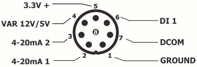 |
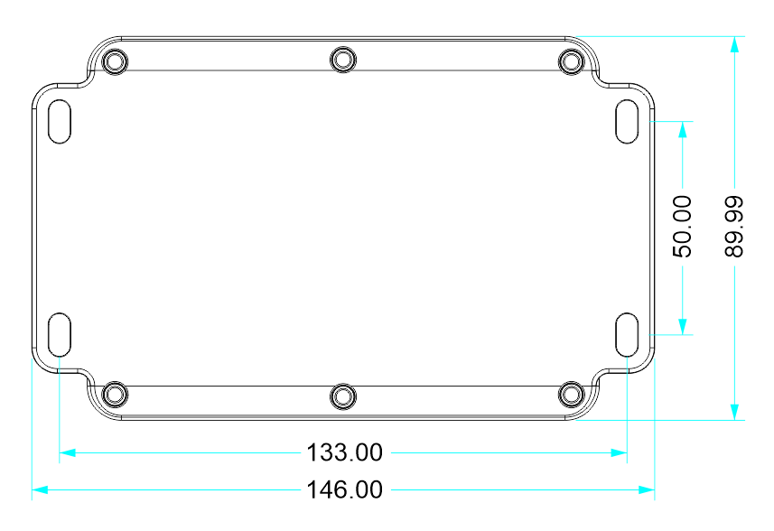
| Length | 146.00 mm |
| Height | 50.00 mm |
| Width | 89.99 mm |
Environment #
| IP degree of protection | IP67 |
| Operating altitude | 2000 meters |
| Operating Temperature | –40 °C to +85 °C |
| Storage Temperature | –45 °C to +90 °C |
| Shock resistance | Operating: 30 g, 11 ms half-sine; Non-operating: 50 g, 11 ms |
| Resistance to electrostatic discharge | Not Applicable |
| Resistance to electromagnetic fields | VBAT/GND: ±5 kV / ±10 kV Antenna: ±5 kV / ±10 kV USB: ±4 kV / ±8 kV UART: ±4 kV / ±6 kV Other pads: ±1 kV / ±2 kV |
Battery Powered Devices #
| Battery Nominal Voltage | 3.6V |
| Battery Capacity | 19000 mAh @ 2.0mA Drain |
| Chemistry of the Battery | Lithium Thionyl Chloride |
| Maximum Continuous Discharge Current | 150mA |
| Maximum Pulse Discharge Current | 300mA |
| Charging source maximum voltage | Not Rechargeable |
Processing #
| SOC / MCU | STM32L072CZT6TR |
| Flash Memory | 192KB Flash |
| ROM | 6 KB |
| SRAM | 20 KB |
| PSRAM | Not available |
Peripherals #
microSD Card support #
| Card Type | microSD |
| Interface | SPI |
| SD CARD CS | PB0 |
| MISO | PA6 |
| MOSI | PA7 |
| SCLK | PA5 |
| SD Detect | Not Implemented |
INPUTS and OUTPUTS #
Analog Inputs #
| Number of Analog Inputs | 2 |
| Analog Inputs Measurement Range | 4 – 20 mA |
| Terminal Arrangement | 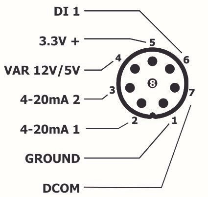 |
Digital Inputs #
| Number of Digital Input | 1 |
| Digital Input Measurement Range | DI – SELECTION 1 -OFF 2 – 3.3V 3 – 5V 4 – 12V |
Cellular Modem #
| Modem | SIMCOM 7070 |
| Technology | LTE Cat-M1 NB-IoT (NB1/NB2) GSM/GPRS fallback (2G) |
| Coverage / Supported Bands | (B1/B2/B3/B4/B5/B8/B12/B13/B18/B19/B20/B26/B27/B28/B66) for Cat-M/NB, plus quad-band GSM (850/900/1800/1900 MHz). |
| Data Rate | LTE Cat-M1: up to 588 kbps DL / 1119 kbps UL NB-IoT: up to 26 kbps DL / 62.5 kbps UL GPRS: 85.6 kbps DL / UL |
| Power Control | PA1 – Active High |
| RX with MCU | PA2 |
| TX with MCU | PA3 |
GPIO Map #
| GPIO | Description |
|---|---|
| PA0 | Not Utilized |
| PA1 | GSM Power Control |
| PA2 | Modem TX with MCU |
| PA3 | Modem RX with MCU |
| PA4 | Power Enable |
| PA5 | SD Card SCLK |
| PA6 | SD Card MISO |
| PA7 | SD Card MOSI |
| PA8 | Not Utilized |
| PA9 | SCL |
| PA10 | SDA |
| PA11 | USB_N |
| PA12 | USB_P |
| PA13 | SWDIO |
| PA14 | SWCLK |
| PA15 | Not Utilized |
| PB0 | SD Card Chip Select |
| PB1 | Not Utilized |
| PB2 | Not Utilized |
| PB3 | Not Utilized |
| PB4 | Not Utilized |
| PB5 | Not Utilized |
| PB6 | Not Utilized |
| PB7 | Not Utilized |
| PC13 | Digital Input |


