In this document, we explore integrating Norvi IIoT devices with MQTT protocol, publishing data and decoding the data by MQTT broker, and visualization in a DATA cake.
MQTT PROTOCOL #
MQTT (Message Queuing Telemetry Transport) is a lightweight messaging protocol designed for low-bandwidth, high-latency, or unreliable networks. It’s widely used in Internet of Things (IoT) and machine-to-machine (M2M) communication due to its simplicity and efficiency.
Check this link to understand more about the MQTT PROTOCOL.
Here are the components of MQTT,
1. Publisher-Subscriber Model
- MQTT follows a publisher-subscriber model. In this model, there are two main entities, publishers and subscribers.
- Publishers are devices or applications that publish messages on a specific topic.
- Subscribers are devices or applications that receive messages by subscribing to specific topics.
2. Broker
- MQTT communication is facilitated by a broker. The broker is a server responsible for receiving, routing, and delivering messages.
- Publishers and subscribers connect to the broker to send and receive messages.
- The broker is responsible for managing topics, subscribers, and message delivery.
3. Topics
- Publishers send MQTT messages to hierarchical topics, which act like addresses.
- Subscribers can subscribe to entire topics or specific subtopics using wildcards.
- For example, a topic could be sensors/temperature where sensors are the main topic and temperature is a subtopic.
4. Retained Messages
- The broker stores retained MQTT messages and sends them to new subscribers immediately when they subscribe.
- This feature is useful for sending status updates or configuration information to new subscribers.
5. Quality of Service (QoS)
- MQTT supports different levels of Quality of Service (QoS) for message delivery:
- MQTT delivers QoS 0 messages at most once, without requiring confirmation.
- MQTT ensures that QoS 1 messages reach the recipient at least once, though duplicates can occur.
- With QoS 2, MQTT delivers each message exactly once, guaranteeing no duplicates.
NORVI IIOT with MQTT #
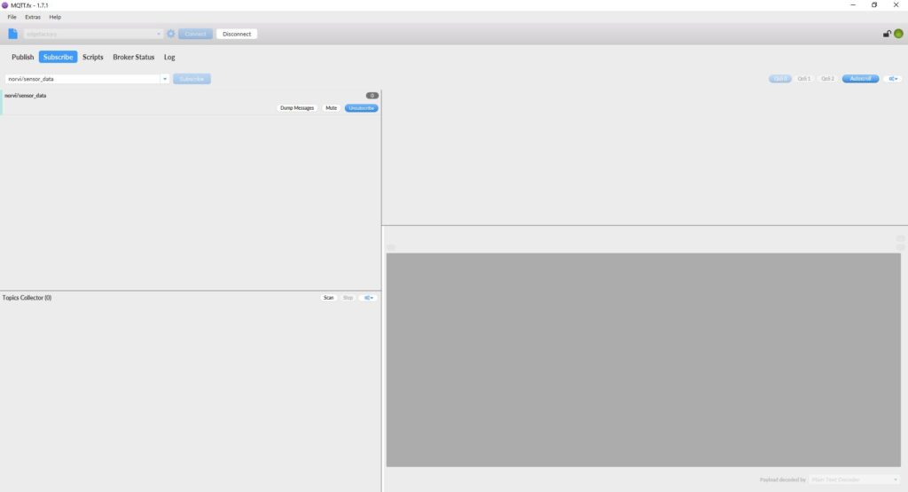
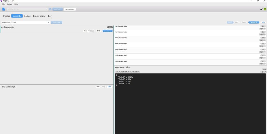
Here we’ll be considering the NORVI ESP32 device as a Publisher and “MQTT.FX” software as the Subscriber. With the NORVI device, we’ll publish the data values of the analog inputs, and store the values in the MQTT Broker and the data visualization platform.
Prerequisites #
- Norvi IIoT device
- MQTT broker
- Subscriber
- Wi-Fi network
- Data visualization platform (e.g., DATACAKE)
Understanding the Test program #
This code connects an ESP32 to a WiFi network and an MQTT broker, reads analog values from an ADS1115 ADC, packages these values into a JSON payload, and publishes the payload to an MQTT topic at regular intervals. It ensures continuous connectivity to the MQTT broker and handles reconnection if the connection drops. Download the example program.
Check the pin configuration of the program according to the NORVI device. Compile and Upload the program.
Include Libraries: The code includes the necessary libraries for WiFi connectivity, MQTT communication, JSON objects, and ADS1115. Find the necessary libraries from here.
#include <WiFi.h>
#include <PubSubClient.h>
#include <ArduinoJson.h>
#include <Adafruit_ADS1X15.h>
WiFi Credentials: Defines the WiFi network name (SSID) and password.
const char* ssid = "YOUR_WIFI_SSID";
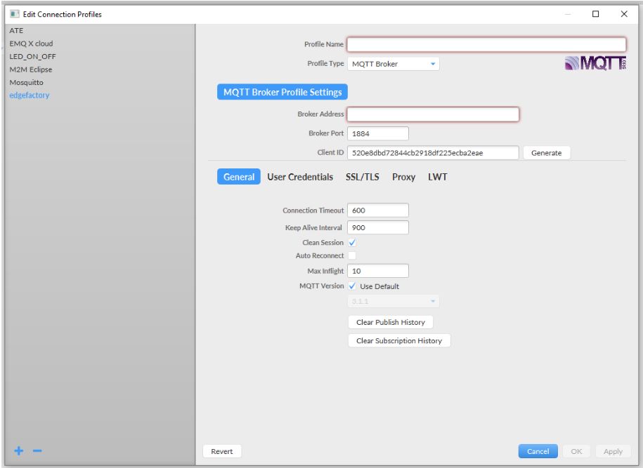
const char* password = "YOUR_WIFI_PASSWORD";MQTT Broker Configuration: Sets up the MQTT broker details including server address, port, topic to publish, and authentication credentials.
const char* mqtt_server = "YOUR_MQTT_BROKER_ADDRESS";
const int mqtt_port = "YOUR_MQTT_PORT";
const char* mqtt_topic = "YOUR_MQTT_TOPIC";
const char* mqtt_username = "YOUR_MQTT_USERNAME";
const char* mqtt_password = "YOUR_MQTT_PASSWORD";
WiFi Client, MQTT Client, and ADS1115 Initialization: initializes the WiFi client, MQTT client, and ADS1115 ADC objects.
WiFiClient espClient;
PubSubClient client(espClient);
Adafruit_ADS1115 ads;
WiFi Connection Setup: Connects to the WiFi network using the provided credentials.
void setup_wifi() {
  delay(10);
  // Connect to WiFi network
  Serial.println();
  Serial.print("Connecting to ");
  Serial.println(ssid);
  WiFi.begin(ssid, password);
  while (WiFi.status() != WL_CONNECTED) {
    delay(500);
    Serial.print(".");
  }
  Serial.println("");
  Serial.println("WiFi connected");
  Serial.println("IP address: ");
  Serial.println(WiFi.localIP());
}
MQTT reconnects the client to the broker whenever the connection drops.
void reconnect() {
  // Loop until we're reconnected
  while (!client.connected()) {
      Serial.println("");
      Serial.print("Attempting MQTT connection...");// Attempt to connect
    if (client.connect("ESP32Client", mqtt_username, mqtt_password)) {
      Serial.println("connected");
    } else {
      Serial.print("failed, rc=");
      Serial.print(client.state());
      Serial.println(" try again in 5 seconds");
// Wait 5 seconds before retrying
      delay(5000);
    }
  }
}
Setup Function: Initializes serial communication, MQTT broker server and port, WiFi connection, I2C communication, and ADS1115 with I2C address 0x48.
void setup() {
  Serial.begin(115200);
  setup_wifi();
  client.setServer(mqtt_server, mqtt_port);
  Wire.begin(16,17);
  if (!ads.begin(0x48)) {
  Serial.println("Failed to initialize ADS.");
  while (1);
  }
}
Loop Function: Reconnects to MQTT if disconnected, then reads ADS data, publishes it to the MQTT broker, and creates JSON Payload.
void loop() {
  int16_t adc0, adc1, adc2, adc3;
  adc0 = ads.readADC_SingleEnded(0); adc1 = ads.readADC_SingleEnded(1);
  adc2 = ads.readADC_SingleEnded(2);adc3 = ads.readADC_SingleEnded(3);
  Serial.println("");
  Serial.print("AIN0: "); Serial.print(adc0);
  Serial.print("\nAIN1: "); Serial.print(adc1);
  Serial.print("\nAIN2: "); Serial.print(adc2);
  Serial.print("\nAIN3: "); Serial.print(adc3);
  Serial.println("");
   if (!client.connected()) {
    reconnect();
  }
  client.loop();
  // Create JSON payload
  DynamicJsonDocument doc(256);
  doc["Anint1"] = adc0;doc["Anin2"] = adc1;
  doc["Anin3"] = adc2;doc["Anin4"] = adc3;
  String payload;
  serializeJson(doc, payload);
  // Publish payload to MQTT topic
  client.publish(mqtt_topic, payload.c_str());
  delay(5000); // Adjust the delay according to your needs
}
Software Configurations #
Check this link for detailed instructions on how to configure the MQTT broker and the Subscriber.
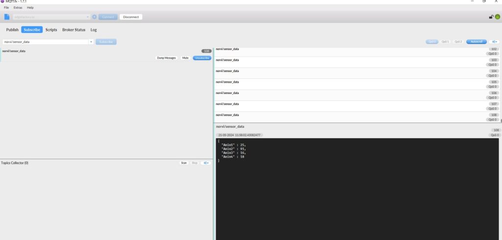
Results from MQTT conversion using the NORVI device. #
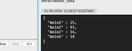
JSON Encoding #
JSON (JavaScript Object Notation) is a lightweight data-interchange format that is easy for humans to read and write and easy for machines to parse and generate. The code structures sensor data (both analog and digital) in JSON before publishing it to the MQTT broker.
Steps of JSON Encoding in the Code,
- The ArduinoJson library is used to handle JSON encoding. It allows us to create a JSON document and serialize it into a string format.
#include <ArduinoJson.h>- A DynamicJsonDocument object named doc is created with a capacity of 256 bytes. This object will hold the JSON structure.
DynamicJsonDocument doc(256);- Each piece of sensor data is added to the doc object as a key-value pair. The keys (e.g., “Analog input1”, “Analog input2”) are strings, and the values (e.g., adc0, adc1) are the sensor readings.
doc["Anin1"] = adc0;
doc["Anin2"] = adc1;
doc["Anin3"] = adc2;
doc["Anin4"] = adc3;- The serializeJson function converts the JSON document (doc) into a string (payload). You can use this string to transmit the data over MQTT.
String payload;
serializeJson(doc, payload);- The payload.c_str() function call converts the String object to a C-style string (a null-terminated array of characters). The MQTT client’s publish method requires this JSON string, which it sends to the specified topic.
client.publish(mqtt_topic, payload.c_str());Integration with Data Visualization Platform #
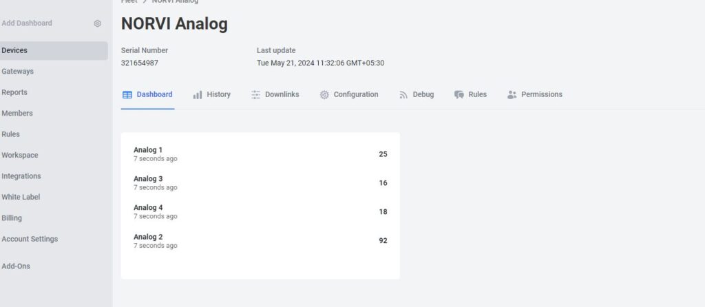
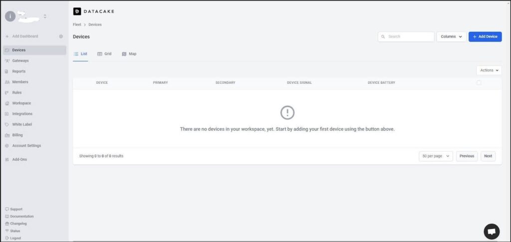
Users can connect NORVI devices to an IoT platform to visualize the data they collect. The platform used in this case is DATACAKE. Here’s how to integrate the NORVI devices with DATACAKE.
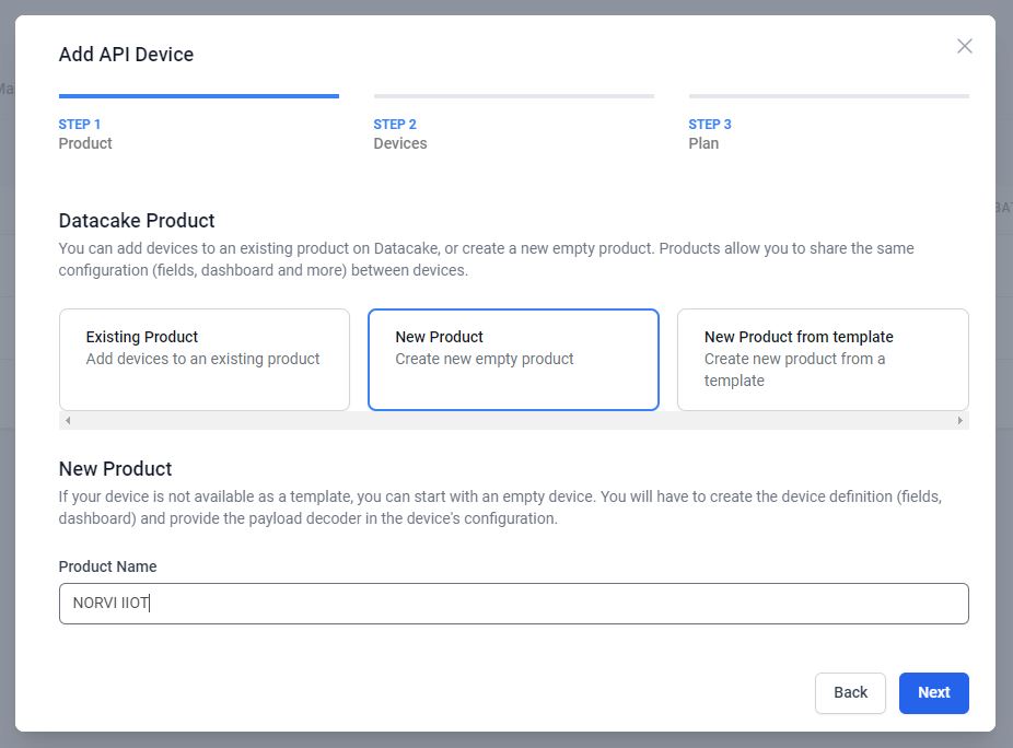
1. Access the DATACAKE from this link and navigate the Datacake dashboard. Select the “Add Devices”.
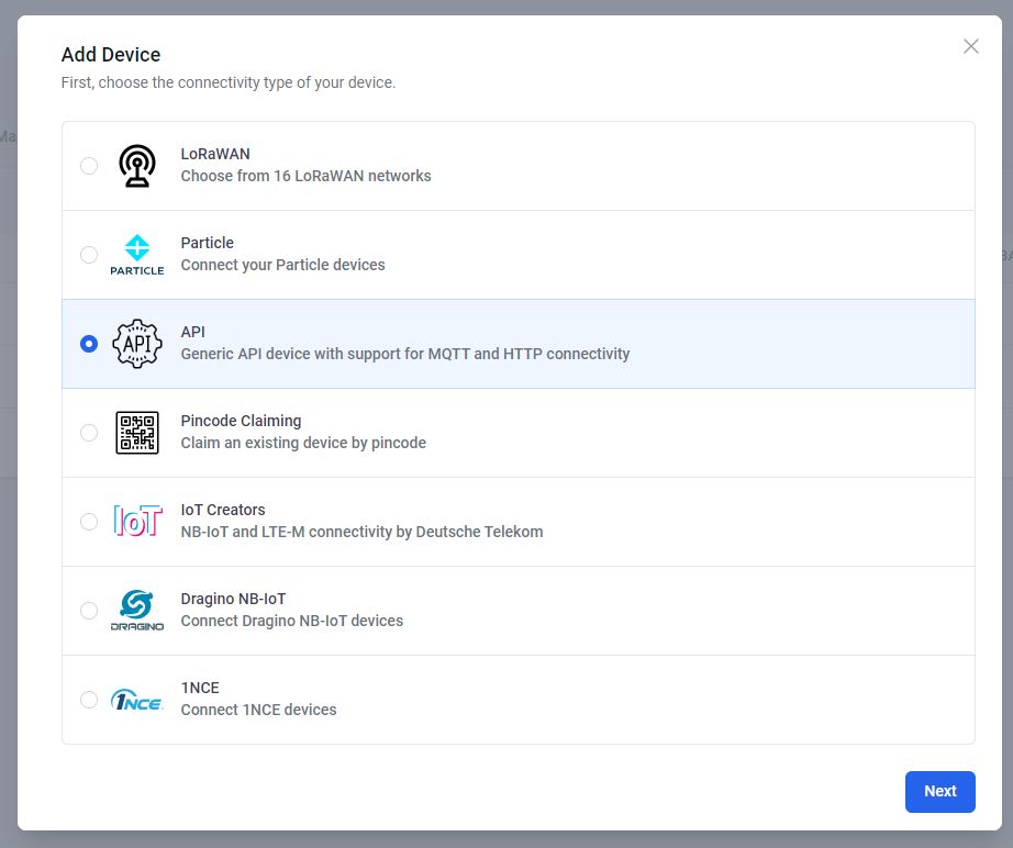
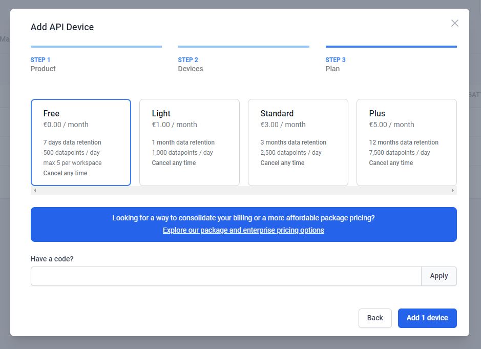
2. For the MQTT integration select the API. This will add the device to the Datacake account.
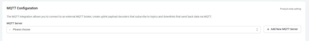
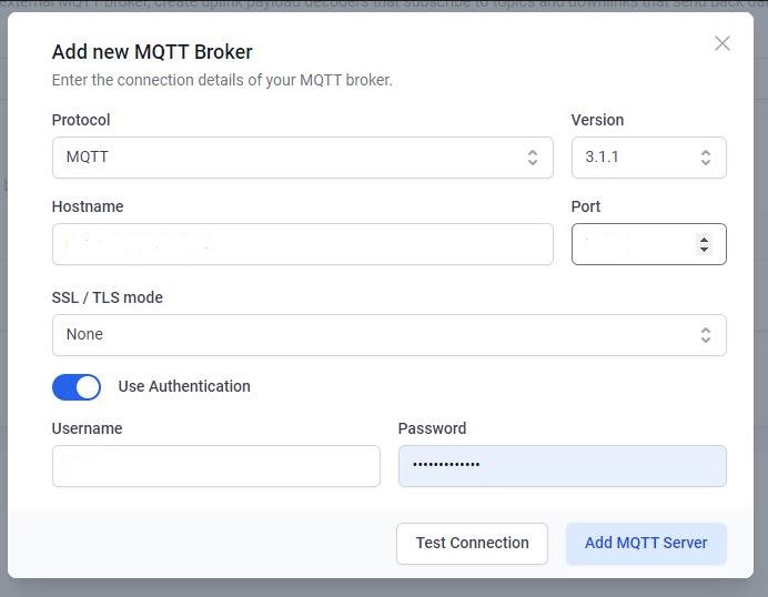
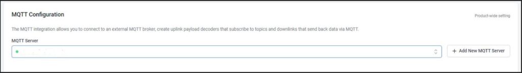
3. Click on Configuration Scroll down a bit and go to the new panel “MQTT Configuration”. Press on “Add New MQTT Broker”. Fill in the server details and add.
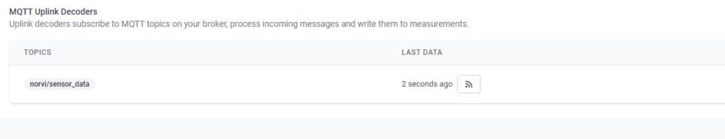
4. Then link the MQTT device on the broker to the device in the DATACAKE by providing the MQTT upline decoder. Subscribe to the topic on the MQTT broker and write a payload decoder.
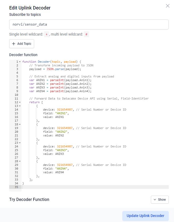
This decoder function decodes incoming device messages and formats them for sending to the Datacake API for display or storage.
JSON Parsing: This function starts by converting the incoming payload, presumably in JSON format, into a JavaScript object. It uses JSON.parse() to accomplish this.
function Decoder(topic, payload) {
  // Transform incoming payload to JSON
  payload = JSON.parse(payload);
}
Data Extraction: It then extracts analog (ANIN1, ANIN2, ANIN3) and digital (INPUT1, INPUT2, INPUT3, INPUT4) inputs from the payload. Each value is converted to an integer using parseInt(). This assumes that the payload contains these fields as strings representing integer values.
// Extract analog and digital inputs from payload
var ANIN1 = parseInt(payload.Anin1);
var ANIN2 = parseInt(payload.Anin2);
var ANIN3 = parseInt(payload.Anin3);
var ANIN4 = parseInt(payload.Anin4);
Data Forwarding: Finally, it constructs an array of objects where each object represents a data point to be sent to the Datacake Device API.
// Forward Data to Datacake Device API using Serial, Field-Identifier
return [
{
device: "Serial Number", // Serial Number or Device ID
field: "ANIN1",
value: ANIN1
},
{
device: "Serial Number", // Serial Number or Device ID
field: "ANIN2",
value: ANIN2
},
{
device: "Serial Number", // Serial Number or Device ID
field: "ANIN3",
value: ANIN3
},
{
device: "Serial Number", // Serial Number or Device ID
field: "ANIN4",
value: ANIN4
}
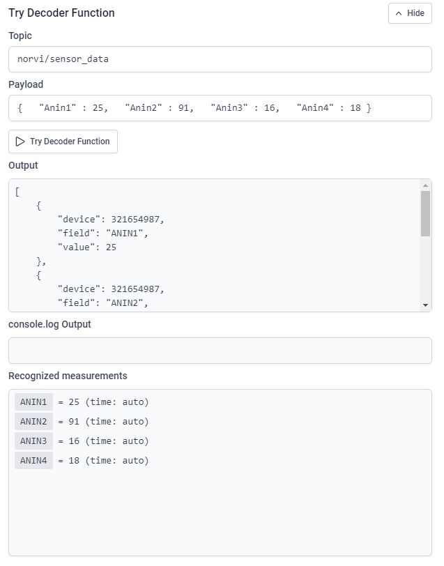
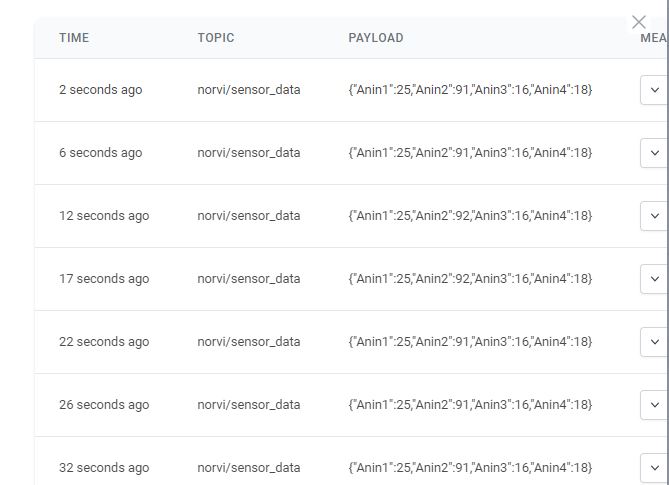
];“Try Decoder Function” allows the decoder function to be tested to verify its functionality before deploying it. By entering sample data and observing the output, you can verify that the decoder is correctly parsing incoming payloads and formatting the data in a way that can be sent to the Datacake API.
5. To create a first database field, click on the “Add Field”. This will open another modal asking for some required input for the fields.
When typing the name for that field, the identifier auto-fills. This identifier is unique and cannot be changed. it’s required for accessing the field from within the payload decoder or API.
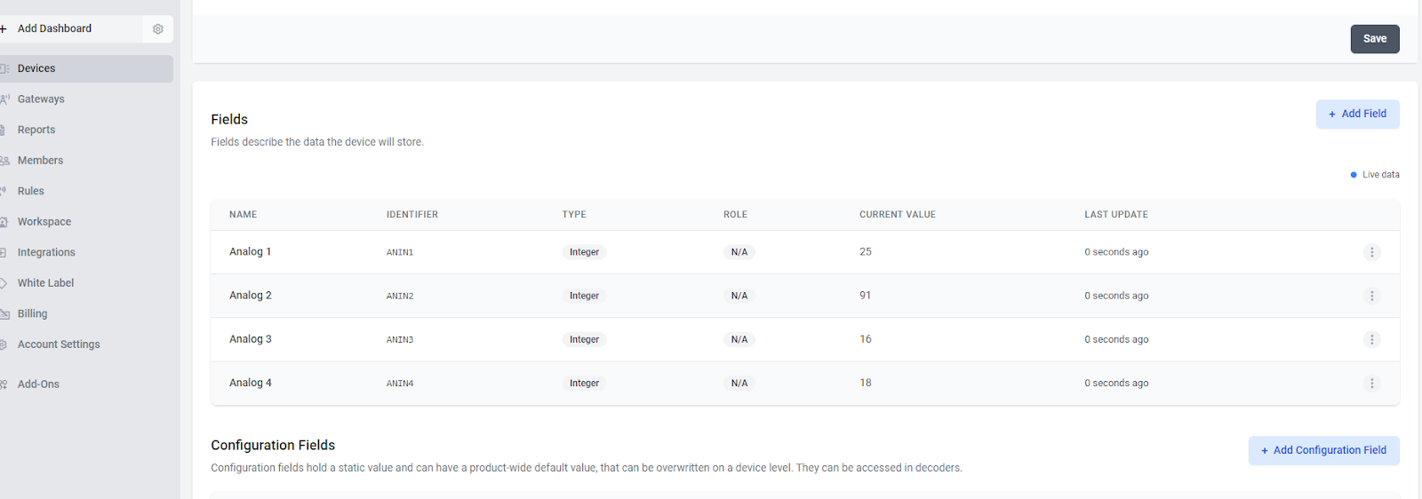
6. If the device is already sending data, an indication of incoming data can be seen in the “Last data” column.
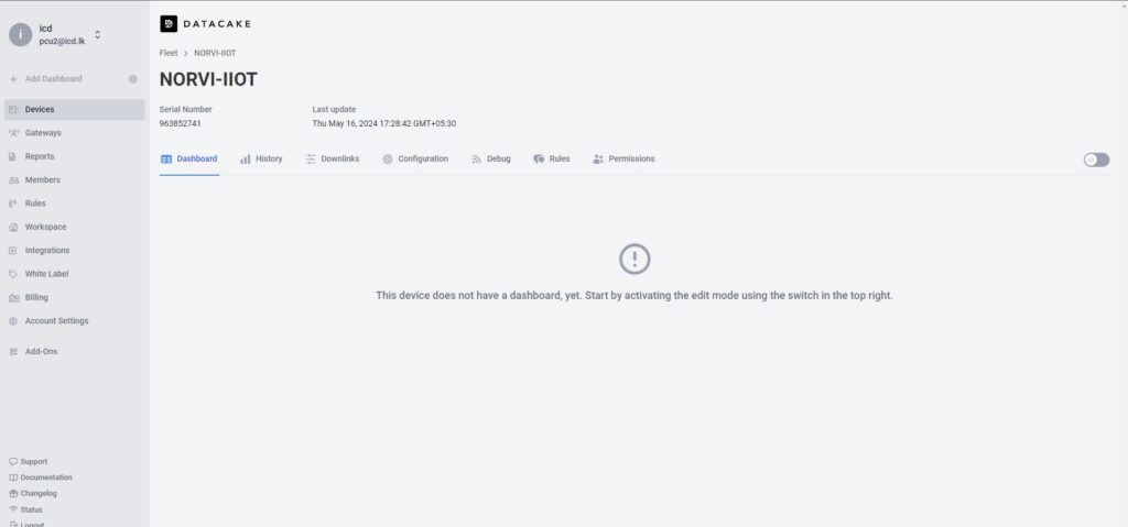
7. After the settings in the configuration section, the dashboard can be created. Use the Tab Bar on the Device to navigate into the “Dashboard” view.