
NORVI devices are cutting-edge technological solutions designed to enhance efficiency, connectivity, and control in various industries. Leveraging advanced IoT technology, NORVI devices offer seamless integration with existing infrastructure, providing real-time monitoring, analytics, and automation capabilities.
In this document, we will explore the process of NORVI acting as a MODBUS slave. We will focus on the interaction between the NORVI device and MODBUS Master software, examining how the system reads digital and analog inputs, stores the values in the MODBUS software, and controls the relay and transistor outputs from the software.
MODBUS Protocol #
MODBUS is a serial communication protocol that Modicon developed and published in 1979 for use with its programmable logic controllers (PLCs). Simply put, it transmits information over serial lines between electronic devices. The device requesting information acts as the MODBUS Master (Client), while the devices providing information act as MODBUS Slaves (Servers). A standard MODBUS network has one master and up to 247 Slaves, each with a unique Slave ID from 1 to 247. The master can also write information to the Slaves.
Several versions of the MODBUS protocol exist for the serial port and Ethernet and the most common are:
- MODBUS RTU
- MODBUS ASCII
- MODBUS TCP
- MODBUS Plus
How does it work? #
MODBUS transmits data over serial lines between devices. The simplest setup uses a single serial cable connecting the serial ports of two devices – a Client and a Server. The system sends data as a series of ones and zeroes called bits, transmitting zeroes as positive voltages and ones as negative. The bits are transmitted very quickly. A typical transmission speed is 9600 baud (bits per second).
Check this link to understand more about the MODBUS protocol.
RTU (RS485) Mode #
MODBUS RTU, designed specifically for serial communication, uses interfaces such as RS-232 or RS-485. When controllers communicate on a MODBUS network in RTU (Remote Terminal Unit) mode, each 8-bit byte in a message contains two 4-bit hexadecimal characters. This mode’s higher character density improves data throughput compared to ASCII at the same baud rate. Each message transmits as a continuous stream.
The format for each byte in RTU mode is:
Coding System
- 8-bit binary, hexadecimal 0-9, A-F
- Two hexadecimal characters are contained in each
- 8-bit field of the message
Bits per Byte
- 1 start bit
- 8 data bits, the least significant bit sent first
- 1 bit for even/odd parity; no bit for no parity
- 1 stop bit if parity is used; 2 bits if no parity
Error Check Field
- Cyclical Redundancy Check (CRC)
RS485 communication in the NORVI devices #
MODBUS functionality is available across all NORVI devices supporting RS485 connectivity. NORVI devices feature an integrated MAX485 driver, with RX, TX, and FC pins directly connected to the corresponding GPIOs. The opposing terminals of the MAX485 driver are labeled A and B.
For specific RS485 GPIO allocations of the NORVI devices, refer to the NORVI RS485 GPIO Allocation.
However, you cannot use serial print functions directly for communication on the NORVI-IIOT-AE01 and NORVI-IIOT-AE02 product ranges because the RS485 TX and RX pins share the same physical pins as the USB RX and TX. As a solution for such situations, we can display the result in the OLED display as described in the troubleshooting section.
NORVI as a MODBUS RTU SLAVE #
The MODBUS protocol has many versions, but this instructable uses MODBUS RTU. Here, we use the simplest configuration, with the NORVI ESP32 device acting as the slave and the “MODBUS Master” software as the master. The NORVI device reads digital and analog inputs and stores the values in the MODBUS software, while the software controls the relay and transistor outputs.
Here we are using the NORVI-IIOT-AE04-V device.
Requirements to get started NORVI device as a slave
- The NORVI device
- Wires for connection
- USB cable.
- USB to RS-485 Converter module.
- MODBUS master device or simulator.
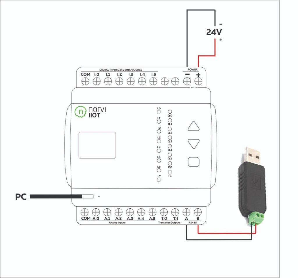
Circuit Connection #
Connect the RS485 A & B pins of the NORVI device with the A & B pins of the USB to the RS-485 converter module.
Power up the device and connect the USB cable.
Connect the USB to the RS-485 converter module to the PC.
Writing the Test Program #
We need to write the program for reading the digital inputs, and analog input and storing the values in the MODBUS master Software. The relay/transistor outputs are controlled by the MODBUS master software.
Download the example program from here.
Check the pin configuration of the program according to the NORVI device.
Compile and Upload the program.
Understanding the Test Program #
Add the required libraries.
- Modbus-esp8266
- Adafruit GFX
- Adafruit ADS1x15
#include <Wire.h>
#include <SPI.h>
#include <Adafruit_ADS1X15.h>
#include <ModbusRTU.h>
Define the Slave ID, RX, TX, and FC and the Inputs and Outputs of the device
#define SLAVE_ID 5
#define RXD 33
#define TXD 2
#define FC  4

#define INPUT1 18
#define INPUT2 34
#define INPUT3 35
#define INPUT4 19

#define OUTPUT1 26
#define OUTPUT2 27
Create Objects for the libraries.
ModbusRTU mb;
Adafruit_ADS1115 ads1;
Setup Function #
Initialize the Serial Monitor at a baud rate of 9600 and RS-485 serial connection. Here Serial1 is the RS485 serial connection. Initialize I2C by setting the SDA and SCL GPIOs to communicate with the ADC. Call the Slave ID. Defined the pin mode of each input and output.
void setup() {
  Serial.begin(9600);
  Serial1.begin(9600, SERIAL_8N1, RXD, TXD);
  mb.begin(&Serial1, FC); // Use Serial for USB communication
  mb.setBaudrate(9600);
  Serial.println("Modbus Initialized");

  Wire.begin(16, 17);
  ads1.begin();
  Serial.println("ADS Initialized");

  pinMode(INPUT1, INPUT);
  pinMode(INPUT2, INPUT);
  pinMode(INPUT3, INPUT);
  pinMode(INPUT4, INPUT);

  pinMode(OUTPUT1, OUTPUT);
  pinMode(OUTPUT2, OUTPUT);
}
Loop Function #
Holding registers are used to store and read analog input status.
void loop() {
  int16_t adc0, adc1, adc2, adc3;

  mb.addHreg(1);
  mb.Hreg(1, adc0);
  mb.addHreg(2);
  mb.Hreg(2, adc1);
  mb.addHreg(3);
  mb.Hreg(3, adc2);
  mb.addHreg(4);
  mb.Hreg(4, adc3);
Discrete input coils are used to store and read the digital input status.
mb.slave(SLAVE_ID);
mb.addIsts(1);
mb.Ists(1, digitalRead(INPUT1));
mb.addIsts(2);
mb.Ists(2, digitalRead(INPUT2));
mb.addIsts(3);
mb.Ists(3, digitalRead(INPUT3));
mb.addIsts(4);
mb.Ists(4, digitalRead(INPUT4));
Discrete output coils are used to control the status of the transistor/relay outputs.
mb.slave(SLAVE_ID);
mb.addCoil(1);
mb.Coil(1);
mb.addCoil(2);
mb.Coil(2);

if (mb.Coil(1) == 1)
{
  digitalWrite(26, HIGH);
}
else
{ digitalWrite(26, LOW);
}

if (mb.Coil(2) == 1)
{
   digitalWrite(27, HIGH);
}
else
{ digitalWrite(27, LOW);
}
These lines will print the status of the digital inputs, status of the transistor/relay outputs, and status of the analog inputs.
Serial.println("\nInputs:");
  Serial.print("Input 1: ");
  Serial.println(digitalRead(INPUT1));
  Serial.print("Input 2: ");
  Serial.println(digitalRead(INPUT2));
  Serial.print("Input 3: ");
  Serial.println(digitalRead(INPUT3));
  Serial.print("Input 4: ");
  Serial.println(digitalRead(INPUT4));

  Serial.print("\nTransistor outs\n");
  Serial.print(" ");
  Serial.println(digitalRead(OUTPUT1));
  Serial.print(" ");
  Serial.println(digitalRead(OUTPUT2));

  Serial.print("\nVoltages\n");
  Serial.print(" ");
  Serial.println(adc0);
  Serial.print(" ");
  Serial.println(adc1);
  Serial.print(" ");
  Serial.println(adc2);
  Serial.print(" ");
  Serial.println(adc3);
Initiate the MODBUS connection between the MODBUS software and the device.
mb.task();
yield();
Result of the NORVI device as a MODBUS RTU SLAVE #
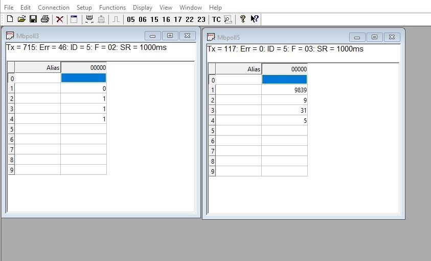
- Read Analog Input
Send the request after changing the serial settings and building a request string.
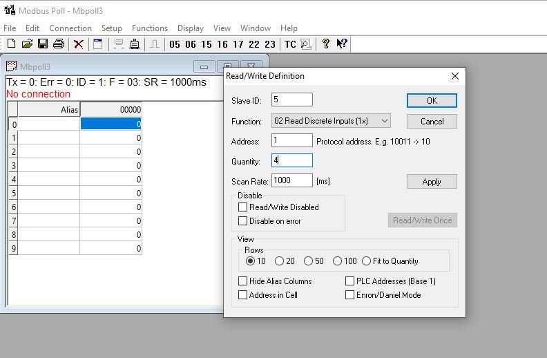
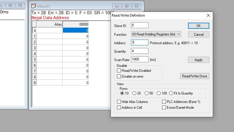
Then the response is displayed in the response table. The initial values are shown below.
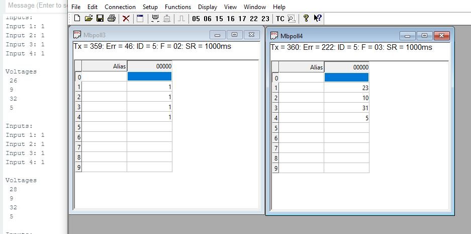
Change the slave values. The changing values are displayed in the response table.
Troubleshooting #
RS485 Check #
Before uploading the MODBUS code, RS485 two ways can be checked by setting the FC pin high and low. This test program sets up communication between two serial ports, the hardware serial port (Serial) and a software serial port (Serial1).
Download the RS485 example program from here and check the pin configuration of the program.
Here’s a breakdown of what each part of the code does,
Defined the FC (Flow Control) pin, RXD (Receive Data) pin and the TXD (Transmit Data) pin.
#define RXD 33
#define TXD 2
#define FC  4
Setup function #
Initializes the hardware serial port (Serial) with a baud rate of 9600 bits per second. Initializes the software serial port (Serial1) with a baud rate of 9600 bits per second, 8 data bits, no parity bit, and 1 stop bit. It also specifies the RXD and TXD PINs defined earlier. Sets the Flow Control pin (FC) as an output pin.
void setup() {
 Serial.begin(9600);
 pinMode(FC, OUTPUT);
 Serial1.begin(9600, SERIAL_8N1,RXD,TXD);
}
Loop function #
Sets the Flow Control pin (FC) to HIGH, indicating that the Arduino is ready to transmit data. Sends the message “RS485 01 SUCCESS” over the RS485 protocol using the software serial port (Serial1). Then sets the Flow Control pin (FC) to LOW, indicating that the Arduino is ready to receive data.
void loop() {
  digitalWrite(FC, HIGH);                    // Make FLOW CONTROL pin HIGH
  Serial1.println(F("RS485 01 SUCCESS"));    // Send RS485 SUCCESS serially
  delay(500);                                // Wait for transmission of data
  digitalWrite(FC, LOW) ;                    // Receiving mode ON
  // Serial1.flush() ;
While loop checks if there is data available to read from the software serial port (Serial1). If there is data available: Reads a character from the software serial port and stores it in the variable n. Writes the character c to the hardware serial port.
while (Serial1.available()) { // Check if data is available
char c = Serial1.read(); // Read data from RS485
Serial.write(c); // Print data on serial monitor
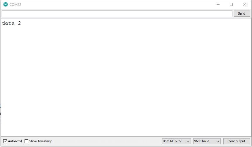
}Software serial window #
Once open both serial windows are open, enter the message into the serial window and send it. From this RS485 can check for both sides.
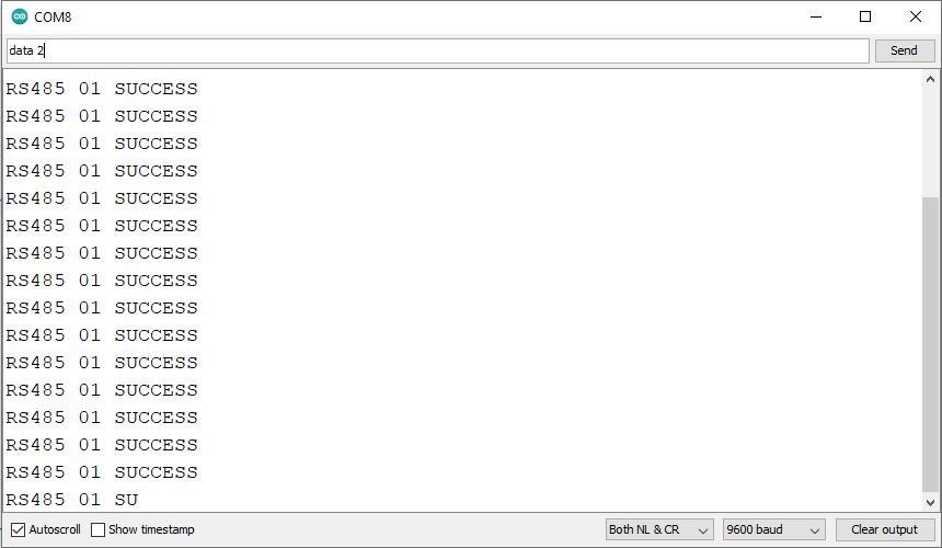
Hardware serial window #
Sharing RX and TX with USB (NORVI IIOT AE01/NORVI IIOT AE02) #
NORVI-IIOT-AE01 and NORVI-IIOT-AE02 product ranges utilize RS485 communication where the TX (Transmit) and RX (Receive) pins are shared with the USB RX and TX pins. This means that the same physical pins are used for both serial communication with a computer via USB and RS485 communication.
As a result, direct use of serial print functions for communication is not possible when connected to such devices. An alternative solution would be to output the result to an OLED display, providing visual feedback on the data.
Before uploading the MODBUS code, RS485 two ways can be checked by setting the FC pin high and low. Download the RS485 example program from here and check the pin configuration of the program.
Download the example program from here.
This program sets up a NORVI-IIOT-AE02 device acting as a MODBUS slave. It reads holding registers from the slave and displays the values on an OLED display.
For specific RS485 GPIO allocations for NORVI devices, refer to the NORVI RS485 GPIO Allocation.
we are using the NORVI-IIOT-AE02 device. It has common RX and TX pins.
- RS485_RX – 3
- RS485_TX – 1
- RS485_FC – 4
- USB_RX – 3
- USB_TX – 1
Add the required libraries.
- Modbus-esp8266
- Adafruit GFX
- Adafruit SSD1306
Defines the screen width, height, and reset pin for the OLED display. Initializes the SSD1306 display object with these parameters.
#include <Wire.h>
#include <Adafruit_SSD1306.h>
#include <Adafruit_GFX.h>
#include <ModbusRTU.h>
Defines the screen width, height, and reset pin for the OLED display. Initializes the SSD1306 display object with these parameters. Then defines the MODBUS slave ID, RX, TX, and the function code and the Inputs and Outputs of the device.
#define SCREEN_WIDTH 128
#define SCREEN_HEIGHT 64
#define OLED_RESET    -1
Adafruit_SSD1306 display(SCREEN_WIDTH, SCREEN_HEIGHT, &Wire, OLED_RESET);

#define SLAVE_ID 5
#define RXD 3
#define TXD 1
#define FC  4
//
#define INPUT1 18
#define INPUT2 39
#define INPUT3 34
#define INPUT4 35
Declares an instance of the MODBUS RTU class.
ModbusRTU mb;Setup function #
Initializes the serial communication, establishes MODBUS RTU communication with the specified function code, sets the Arduino pin corresponding to the function code to LOW, initializes MODBUS RTU as master, initiates I2C communication with the specified pins for the OLED display, and initializes the display. Defined the pin mode of each input.
void setup() {
  //Serial.begin(9600);
  Serial.begin(9600, SERIAL_8N1,RXD,TXD);
  mb.begin(&Serial1, FC); // Use Serial for USB communication
  mb.setBaudrate(9600);
  Serial.println("Modbus Initialized");

  //Initialize Digital Inputs
  pinMode(INPUT1, INPUT);
  pinMode(INPUT2, INPUT);
  pinMode(INPUT3, INPUT);
  pinMode(INPUT4, INPUT);

  Wire.begin(16, 17);
  display.begin(SSD1306_SWITCHCAPVCC, 0x3C);
  display.display();
}
Loop function #
Reads Discreat Input Coils from the slave device stored in the master device.
  mb.slave(SLAVE_ID);
  mb.addIsts(1);
  mb.Ists(1,digitalRead(INPUT1));
  mb.addIsts(2);
  mb.Ists(2,digitalRead(INPUT2));
  mb.addIsts(3);
  mb.Ists(3,digitalRead(INPUT3));
  mb.addIsts(4);
  mb.Ists(4,digitalRead(INPUT4));
Then display the readings on the OLED screen of the slave device.
  display.clearDisplay();
  display.setTextColor(WHITE);
  display.setTextSize(1);
  display.setCursor(0, 0);
  display.print("INP 1- "); display.print(digitalRead(INPUT1));
  display.setCursor(70, 0);
  display.print("INP 2- "); display.println(digitalRead(INPUT2));
  display.setCursor(0, 14);
  display.print("INP 3- "); display.print(digitalRead(INPUT3));
  display.setCursor(70, 14);
  display.print("INP 4- "); display.println(digitalRead(INPUT4));


