Digital inputs and outputs for NORVI controllers form the foundation of industrial automation and IoT applications. Whether you’re building a smart factory, agricultural monitoring system, or building automation project, understanding how digital inputs and outputs work with NORVI controllers is essential for successful implementation.
In this comprehensive guide, we’ll explore everything you need to know about digital inputs and outputs on NORVI controllers, from basic concepts to advanced applications.
What Are Digital Inputs and Outputs?
Digital inputs and outputs operate in binary states: ON or OFF, HIGH or LOW, 1 or 0. This simplicity makes digital IO incredibly reliable for industrial applications where you need clear, unambiguous communication between devices.
Digital inputs allow your NORVI controller to read the status of external devices like switches, sensors, buttons, and relay contacts. When a sensor detects motion or a button is pressed, the digital input registers this change, enabling your NORVI controller to respond accordingly.
Digital outputs enable your NORVI controller to control external devices such as motors, valves, relays, indicator lights, and alarms. By switching digital outputs ON or OFF, you can automate processes, trigger alerts, or control industrial equipment with precision.
How NORVI Controllers Handle Digital Inputs and Outputs
NORVI controllers are ESP32-based industrial IoT controllers designed specifically for harsh industrial environments. Here’s what makes NORVI’s digital inputs and outputs implementation stand out in the industrial automation market.
Optical Isolation for Industrial Safety
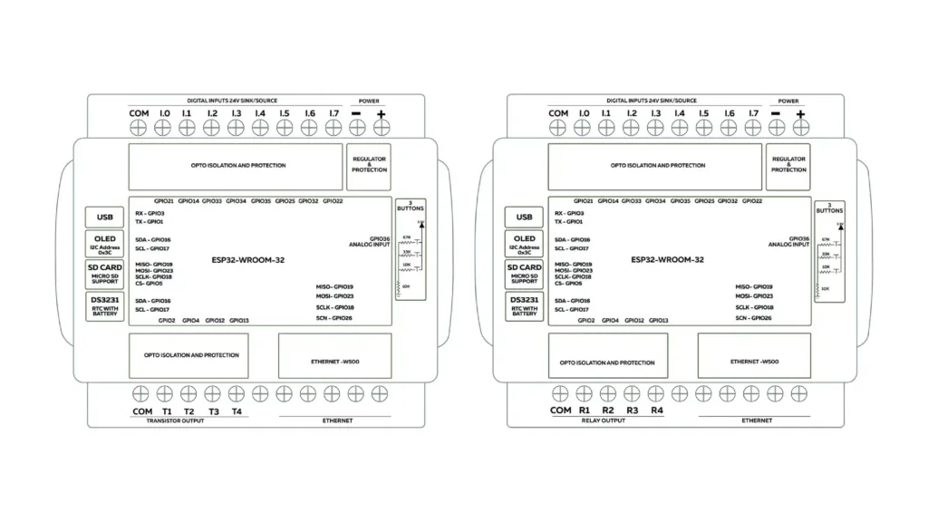
NORVI controllers feature optically isolated digital inputs, typically rated for 24V DC operation. This optical isolation protects your controller’s sensitive electronics from voltage spikes, electrical noise, and ground loops commonly found in industrial settings. Your investment in NORVI controllers stays protected even in harsh electrical environments.
Industrial-Grade Digital Input Specifications
The digital inputs on NORVI controllers are designed to interface directly with standard industrial sensors and switches:
- Voltage Rating: 24V DC (industry standard for industrial automation)
- Isolation: Optical isolation for superior noise immunity
- Protection: Built-in protection against reverse polarity and overvoltage
- Compatibility: Works with both PNP and NPN type sensors
Flexible Digital Output Options
NORVI controllers offer multiple digital output types to suit different industrial applications:
Relay Outputs: Perfect for switching high-power AC or DC loads up to 5A at 250VAC/30VDC. These mechanical relay outputs are ideal for controlling pumps, motors, solenoids, and lighting systems in industrial automation.
Transistor Outputs: Solid-state digital outputs for faster switching and longer operational life. These optically isolated transistor outputs handle loads up to 24V DC and are perfect for controlling PLCs, indicators, and low-power devices.
Real-World Applications of Digital Inputs and Outputs
Understanding how to leverage digital inputs and outputs on NORVI controllers opens up countless industrial automation possibilities.
Machine Monitoring and Control
Monitor the operational status of machinery through limit switches and proximity sensors connected to digital inputs. Use digital outputs to start/stop equipment, trigger emergency stops, or activate warning lights when maintenance is needed. NORVI controllers excel at machine monitoring in manufacturing environments.
Conveyor System Automation
Count products moving along a conveyor belt using photoelectric sensors connected to digital inputs on your NORVI controller. Control conveyor motors, diverter gates, and sorting mechanisms through digital outputs, creating sophisticated material handling systems with industrial IoT capabilities.
Building Automation Systems
Interface with door sensors, motion detectors, and push buttons through digital inputs. Control lighting, HVAC systems, access control locks, and alarm systems using digital outputs. NORVI’s Ethernet and WiFi connectivity enable seamless integration with building management systems.
Agricultural IoT Applications
Monitor soil moisture sensors, float switches in water tanks, and greenhouse door status through digital inputs. Automate irrigation valves, ventilation fans, and feeding systems with digital outputs, all while logging data to the cloud via NORVI’s GSM/4G connectivity options.
Energy Management and Smart Grid
Read status from circuit breakers, power meters, and grid connection sensors using digital inputs. Control load switching, generator starting systems, and energy storage systems with digital outputs for smart grid applications.
Programming Digital Inputs and Outputs on NORVI Controllers
One of NORVI’s greatest strengths is programming flexibility for digital inputs and outputs. You can develop industrial automation applications using multiple platforms.
Arduino IDE Programming
The most popular choice for programming NORVI controllers, Arduino IDE offers familiar C/C++ programming with extensive libraries. Simply configure your digital input and output pins, read inputs with digitalRead(), and control outputs with digitalWrite().
NORVI provides comprehensive Arduino examples for digital IO in their GitHub repository. You can find ready-to-use code examples for different controller models:
- NORVI IIOT-AE01-R – Controller with relay outputs
- NORVI IIOT-AE01-T – Controller with transistor outputs
- NORVI IIOT-AE02-I – Controller with 4-20mA analog inputs
Modbus Protocol Integration
NORVI controllers with Modbus support allow seamless integration with SCADA systems, HMIs, and other industrial controllers. Map your digital inputs and outputs to Modbus registers for standardized industrial communication. This makes NORVI controllers compatible with existing PLC networks.
Learn how to implement Modbus communication for reading digital inputs and controlling outputs in the NORVI Modbus RTU Communication Guide.
MQTT and Industrial IoT Platforms
Leverage the ESP32’s connectivity to send digital input states to cloud platforms and receive remote commands to control digital outputs. Perfect for IIoT applications requiring real-time monitoring and control of industrial processes.
Getting Started with NORVI Controller Digital IO
Here’s a practical roadmap for working with digital inputs and outputs on NORVI controllers.
Step 1: Choose the Right NORVI Controller Model
Select a NORVI controller that matches your digital input and output requirements:
- NORVI IIOT Series: ESP32-based controllers with WiFi, offering 4-16 digital inputs and various output configurations
- NORVI ENET Series: Ethernet-enabled controllers with W5500 for reliable wired connectivity
- NORVI GSM Series: Controllers with cellular connectivity for remote locations
- NORVI X Series: Next-generation modular controllers with expandable IO
Step 2: Understanding Digital Input and Output Wiring
For digital inputs, connect your sensors according to the wiring diagram provided with your NORVI controller. Typically, 24V sensors connect between the 24V supply and the input terminal, with the input terminal internally connected through an optocoupler for isolation.
For digital outputs, ensure your load requirements match the output specifications. Relay outputs can handle higher currents but have slower switching times. Transistor outputs switch faster but are limited to 24V DC loads.
Step 3: Install Development Environment
Set up Arduino IDE with ESP32 board support for programming NORVI controllers. NORVI provides comprehensive documentation and example code on their GitHub repository to help you get started quickly with digital inputs and outputs.
Step 4: Write and Test Your Digital IO Code
Start with simple programs that read a single digital input and control a single digital output. Gradually add complexity as you become comfortable with the NORVI controller hardware.
Here’s a basic example for reading digital inputs and controlling outputs on NORVI controllers:
// Define NORVI IIOT pins
#define INPUT1 18
#define INPUT2 39
#define OUTPUT1 26
#define OUTPUT2 27

void setup() {
  Serial.begin(9600);

  // Configure digital inputs
  pinMode(INPUT1, INPUT);
  pinMode(INPUT2, INPUT);

  // Configure digital outputs
  pinMode(OUTPUT1, OUTPUT);
  pinMode(OUTPUT2, OUTPUT);
}

void loop() {
  // Read digital inputs
  int input1State = digitalRead(INPUT1);
  int input2State = digitalRead(INPUT2);

  // Control outputs based on inputs
  if (input1State == LOW) {  // Input activated (24V applied)
    digitalWrite(OUTPUT1, HIGH);  // Turn on output
  } else {
    digitalWrite(OUTPUT1, LOW);
  }

  Serial.print("Input 1: ");
  Serial.println(input1State);
  delay(100);
}
For complete test programs and pin configurations, check the NORVI test programs documentation. Use NORVI’s built-in OLED display for debugging and status indication.
Step 5: Scale Your Industrial Automation Application
Once your basic digital input and output logic works, add advanced features like data logging to the microSD card, remote monitoring via WiFi/Ethernet, or Modbus communication for SCADA integration.
Best Practices for Digital Inputs and Outputs
Input Debouncing
Mechanical switches and relays can bounce, creating multiple rapid transitions on digital inputs. Implement software debouncing by reading inputs multiple times over a short period or using timing delays. This ensures reliable digital input reading on your NORVI controller.
Input Signal Filtering
In electrically noisy industrial environments, add small delays between consecutive digital input reads to filter out transient signals that might cause false triggers. NORVI’s optical isolation helps, but software filtering adds extra protection.
Output Verification and Feedback
After commanding a digital output change, read back the input states to verify that the physical device responded as expected. This closed-loop approach increases industrial automation system reliability with NORVI controllers.
Documentation and Labeling
Keep detailed records of which digital inputs and outputs connect to which field devices. This documentation becomes invaluable during troubleshooting and system modifications of your NORVI controller installation.
Safety-First Design
Always implement emergency stop functionality, watchdog timers, and fail-safe states in your digital output logic. Ensure that if the NORVI controller loses power or encounters an error, your system transitions to a safe condition.
Advanced Features in NORVI Controllers
Beyond basic digital inputs and outputs, NORVI controllers offer features that enhance your industrial automation capabilities.
Real-Time Clock for Time-Based Control
DS3231 Real-Time Clock enables you to timestamp digital input events, schedule digital output operations, and maintain accurate time even during power outages with battery backup.
Data Logging with MicroSD Card
Log digital input state changes, create historical records of output operations, and store configuration files for advanced industrial IoT applications using the built-in microSD card slot.
IO Expansion Modules
Add more digital input and output capacity using I2C-based expansion modules. NORVI offers relay expansion modules, transistor output modules, and analog IO expansions for scalable industrial automation.
RS-485 Modbus Communication
Add more digital input and output capacity using I2C-based expansion modules. NORVI offers:
- Digital Input Expansion (NORVI-EX-I8) – 8 additional isolated digital inputs
- Relay expansion modules – Additional relay outputs
- Transistor output modules – Extra solid-state outputs
These expansion modules connect to your base NORVI controller via I2C, allowing you to scale from basic applications to complex systems with dozens of IO points.
Troubleshooting Digital Inputs and Outputs
Digital Input Not Responding
Check sensor power supply voltage, verify sensor output voltage matches input specifications, ensure proper polarity, and test with a multimeter. NORVI’s optically isolated digital inputs are robust, but external wiring issues can occur.
Diagnostic Code for Testing Digital Inputs:
// Digital Input Diagnostic Test
#define INPUT1 18
#define INPUT2 39
#define INPUT3 34
#define INPUT4 35

void setup() {
  Serial.begin(9600);

  // Configure all inputs
  pinMode(INPUT1, INPUT);
  pinMode(INPUT2, INPUT);
  pinMode(INPUT3, INPUT);
  pinMode(INPUT4, INPUT);

  Serial.println("=== NORVI Digital Input Diagnostic ===");
  Serial.println("Connect 24V to each input to test");
}

void loop() {
  Serial.println("\n--- Input Status ---");
  Serial.print("Input 1: "); Serial.println(digitalRead(INPUT1) ? "OPEN" : "CLOSED (24V)");
  Serial.print("Input 2: "); Serial.println(digitalRead(INPUT2) ? "OPEN" : "CLOSED (24V)");
  Serial.print("Input 3: "); Serial.println(digitalRead(INPUT3) ? "OPEN" : "CLOSED (24V)");
  Serial.print("Input 4: "); Serial.println(digitalRead(INPUT4) ? "OPEN" : "CLOSED (24V)");

  delay(1000);  // Check every second
}
This diagnostic code continuously monitors all digital inputs and reports their status to the Serial Monitor. When functioning correctly, inputs show “OPEN” (value 1) when no voltage is applied, and “CLOSED” (value 0) when 24V is applied.
Digital Output Not Switching
Verify load voltage and current are within digital output specifications, check for blown fuses or damaged components, ensure proper wiring, and test the output with a simple LED and resistor. NORVI relay outputs and transistor outputs have different specifications.
Diagnostic Code for Testing Digital Outputs:
// Digital Output Diagnostic Test with LED Pattern
#define OUTPUT1 26
#define OUTPUT2 27
#define OUTPUT3 14
#define OUTPUT4 12

void setup() {
  Serial.begin(9600);

  // Configure all outputs
  pinMode(OUTPUT1, OUTPUT);
  pinMode(OUTPUT2, OUTPUT);
  pinMode(OUTPUT3, OUTPUT);
  pinMode(OUTPUT4, OUTPUT);

  Serial.println("=== NORVI Digital Output Diagnostic ===");
  Serial.println("Watch for LED indicators and relay clicking");
}

void loop() {
  // Test each output sequentially
  for(int i = 0; i < 4; i++) {
    int outputPin = (i == 0) ? OUTPUT1 : (i == 1) ? OUTPUT2 : (i == 2) ? OUTPUT3 : OUTPUT4;

    Serial.print("Testing Output "); Serial.print(i + 1);
    digitalWrite(outputPin, HIGH);
    Serial.println(" - ON");
    delay(2000);  // Keep on for 2 seconds

    digitalWrite(outputPin, LOW);
    Serial.println(" - OFF");
    delay(500);
  }

  Serial.println("\nCycle complete. Repeating...\n");
  delay(1000);
}
This code cycles through all digital outputs, turning each one ON for 2 seconds. You should see:
- LED indicators light up on the NORVI controller
- Relay outputs make an audible clicking sound
- Transistor outputs show voltage when measured with a multimeter
Combined Input-Output Loop Test:
For testing complete IO functionality, NORVI provides comprehensive test programs that display input states on the OLED screen and cycle through all outputs. Access the complete test program with OLED display integration at the NORVI Test Programs Repository.
Intermittent Operation
Look for loose connections in digital input or output wiring, electromagnetic interference from nearby equipment, inadequate power supply capacity for your NORVI controller, or environmental factors like temperature and moisture affecting sensor operation.
Why Choose NORVI Controllers for Digital IO Applications
NORVI controllers stand out in the industrial IoT market for several reasons:
Industrial-Grade Reliability: Built with industrial-grade components, NORVI controllers handle harsh environments where consumer-grade ESP32 boards fail. The optically isolated digital inputs and outputs ensure long-term reliability.
Cost-Effective Solution: NORVI provides industrial-quality digital inputs and outputs at prices significantly lower than traditional PLCs, making industrial automation accessible to smaller operations and prototyping projects.
Multiple Connectivity Options: Choose from Wi-Fi, Ethernet, GSM/4G, LoRa, and RS-485 connectivity, ensuring your digital input and output data reaches where it needs to go, whether local SCADA systems or cloud platforms.
Easy Programming: Unlike proprietary PLC programming software, NORVI controllers use Arduino IDE, making digital input and output programming accessible to engineers familiar with C/C++ or Python.
Expandable Architecture: Start with basic digital inputs and outputs, then expand with additional modules as your industrial automation needs grow.
Integrating Digital Inputs and Outputs with Industrial Protocols
Modbus TCP/RTU Integration
NORVI controllers support Modbus TCP over Ethernet and Modbus RTU over RS-485, allowing seamless integration of digital inputs and outputs with existing industrial automation systems. Map your IO points to Modbus registers for standard SCADA access.
MQTT for Cloud Connectivity
Publish digital input states and subscribe to digital output commands using MQTT protocol. This enables cloud-based monitoring and control of your industrial IoT applications with NORVI controllers.
REST API Integration
Develop custom REST APIs on your NORVI controller to read digital inputs and control digital outputs via HTTP requests, perfect for web-based dashboards and mobile applications.
Example Applications: Digital Inputs and Outputs in Action
Pump Control System
Use digital inputs to monitor water level sensors (high level, low level) and pump status feedback. Control pump contactors and alarm indicators using digital outputs. Add Modbus communication for SCADA integration with your NORVI controller.
Conveyor Line Monitoring
Connect photoelectric sensors to digital inputs for product counting and jam detection. Control conveyor motors, diverters, and reject mechanisms using digital outputs. Log production data to microSD card for quality tracking.
Environmental Monitoring Station
Monitor door contacts, motion sensors, and alarm inputs using digital inputs. Control ventilation fans, heating elements, and alarm sirens with digital outputs. Send alerts via GSM when digital input conditions are met.
Additional Resources and Learning Materials
To help you master digital inputs and outputs with NORVI controllers, here are essential resources:
Official Documentation
- NORVI Documentation Portal – Complete user guides and tutorials
- Getting Started with NORVI Devices – Step-by-step beginner guide
- Product-specific user guides for NORVI IIOT-AE02-I and NORVI IIOT-AE02-V
GitHub Code Repository
The Industrial Arduino GitHub contains 120+ repositories with example code, including:
- Pin mapping definitions for all controller models
- Complete test programs for verifying digital IO functionality
- Integration examples with ThingsBoard, MQTT, and Modbus
- OTA (Over-The-Air) update examples
- HMI interface examples with Node-RED
Video Tutorials and Community
- NORVI YouTube channel with programming tutorials
- Community support forums for troubleshooting
- Application notes for specific industries
Conclusion: Mastering Digital Inputs and Outputs with NORVI
Digital inputs and outputs are the gateway between your NORVI controller and the physical world of industrial automation. By understanding how to properly configure, wire, and program these fundamental interfaces, you unlock the full potential of industrial IoT with NORVI controllers.
NORVI controllers provide industrial-grade reliability for digital inputs and outputs, multiple connectivity options, and programming flexibility that make them ideal for projects ranging from simple automation tasks to complex IIoT deployments. With proper implementation of digital IO, you can create responsive, reliable systems that monitor conditions, control processes, and communicate data across your entire operation.
Whether you’re building a prototype or deploying a production industrial automation system, NORVI’s comprehensive ecosystem of controllers with digital inputs and outputs, expansion modules, and development tools provides everything you need to bring your automation vision to life. Start with the basics of digital inputs and outputs on NORVI controllers, and progressively add advanced features as your application grows.
Ready to get started with digital inputs and outputs? Visit Home to explore the complete range of NORVI controllers and find the perfect industrial IoT solution for your next project requiring reliable digital inputs and outputs.