Programming #
ESP-HMI-5C-CI has a mini USB Port for serial connection with the SoC for programming. Any ESP32-supported programming IDE can be used to program the controller. Follow this Guide to programming NORVI ESP32 Based Controllers with Arduino IDE.
SoC: ESP32-S3-WROOM32
Programming Port: USB UART
The following settings for the Arduino IDE tools should be changed while programming:
| Board | ESP32-S3 Dev Module , version 2.0.9 |
| USB mode | Hardware CDC and JTAG |
| USB CDC on Boot | Disabled |
| USB firmware MSC on boot | Disabled |
| USB DFU on boot | Disabled |
| Upload mode | UART0 / Hardware CDC |
| Flash size | 16MB |
| PSRAM | OPI PSRAM |
Digital Inputs #
Wiring Digital Inputs #
The digital inputs of ESP-HMI-5C-CI can be configured as both a Sink and Source connection. The inverse of the Digital Input polar should be supplied to the common terminal.

Programming Digital Inputs #
Reading the relevant GPIO of ESP32 gives the value of the Digital Input. When the inputs are in the OFF state the GPIO goes HIGH, and when the input is in the ON stage GPIO goes LOW. Refer to the GPIO allocation table in the Datasheet for the digital input GPIO.
#include "Wire.h"
#define SDA 19
#define SCL 20
#define PCA9538_ADDR 0x73
#define PCA9538_INPUT_REG 0x00
#define PCA9538_CONFIG_REG 0x03
#define GPIO1 0x01
#define GPIO2 0x02
#define GPIO3 0x04
#define GPIO4 0x08
#define NUM_INPUT_PINS 4

void setPinMode(uint8_t pin, uint8_t mode) {
  uint8_t config = readRegister(PCA9538_CONFIG_REG);
  if (mode == INPUT) {
     config |= pin;
   } else {
     config &= ~pin;
   }
   writeRegister(PCA9538_CONFIG_REG, config);
}

uint8_t readInput() {
   return readRegister(PCA9538_INPUT_REG);
}

uint8_t readRegister(uint8_t reg) {
  Wire.beginTransmission(PCA9538_ADDR);
  Wire.write(reg);
  Wire.endTransmission(false);
  Wire.requestFrom(PCA9538_ADDR, 1);
  return Wire.read();
}

void writeRegister(uint8_t reg, uint8_t value) {
  Wire.beginTransmission(PCA9538_ADDR);
  Wire.write(reg);
  Wire.write(value);
  Wire.endTransmission();
}

void setup() {
  Serial.begin(9600);
  Wire.begin(SDA, SCL);
  setPinMode(GPIO1, INPUT);
  setPinMode(GPIO2, INPUT);
  setPinMode(GPIO3, INPUT);
  setPinMode(GPIO4, INPUT);
}

void loop() {
  uint8_t input = readInput();
  bool inputValues[NUM_INPUT_PINS];
  for (int i = 0; i < NUM_INPUT_PINS; i++) {
     inputValues[i] = bitRead(input, i);
     Serial.print( inputValues[i]);
  }
}
Transistor Output #
Wiring Transistor Outputs #
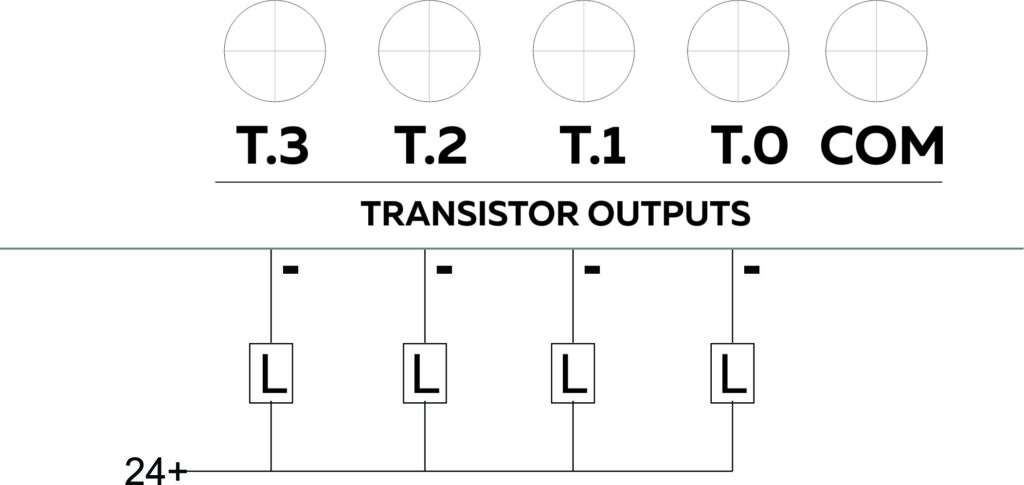
Programming Transistor Outputs #
#include "Wire.h"
#define SDA 19
#define SCL 20
#define PCA9538_ADDR 0x73
#define PCA9538_INPUT_REG 0x00
#define PCA9538_OUTPUT_REG 0x01
#define PCA9538_POLARITY_REG 0x02
#define PCA9538_CONFIG_REG 0x03
#define GPIO5 0x10
#define NUM_OUTPUT_PINS 4

void setPinMode(uint8_t pin, uint8_t mode) {
  uint8_t config = readRegister(PCA9538_CONFIG_REG);
  if (mode == INPUT) {
     config |= pin;
  }
  else {
     config &= ~pin;
  }
  writeRegister(PCA9538_CONFIG_REG, config);
}

void writeOutput(uint8_t pin, uint8_t value) {
  uint8_t output = readRegister(PCA9538_OUTPUT_REG);
  if (value == LOW) {
     output &= ~pin;
  }
  else {
    output |= pin;
  }
  writeRegister(PCA9538_OUTPUT_REG, output);
}

uint8_t readInput() {
  return readRegister(PCA9538_INPUT_REG);
}

uint8_t readRegister(uint8_t reg) {
  Wire.beginTransmission(PCA9538_ADDR);
  Wire.write(reg);
  Wire.endTransmission(false);
  Wire.requestFrom(PCA9538_ADDR, 1);
  return Wire.read();
}

void writeRegister(uint8_t reg, uint8_t value) {
  Wire.beginTransmission(PCA9538_ADDR);
  Wire.write(reg);
  Wire.write(value);
  Wire.endTransmission();
}

void setup() {
  Wire.begin(SDA, SCL);
  setPinMode(GPIO5, OUTPUT);
}

void loop() {
  writeOutput(GPIO5, 0);
  delay(300);
  writeOutput(GPIO5, 1);
  delay(300);
}
4 – 20 Analog Input #
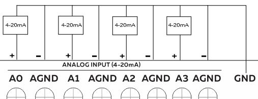
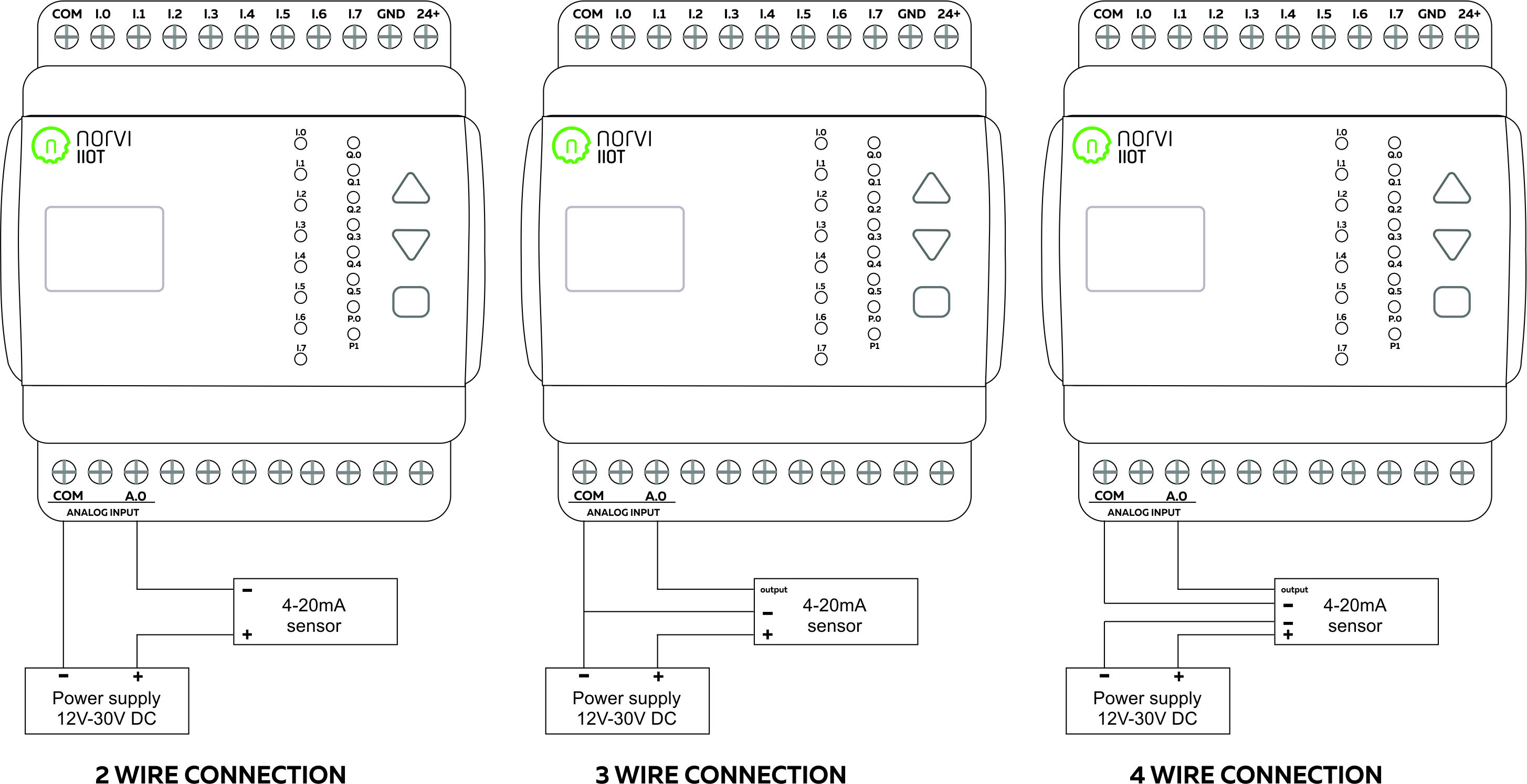
Wiring Analog Inputs #
Reading the relevant I2C address of the ADC gives the value of the Analog Input.
Reading Analog Input #
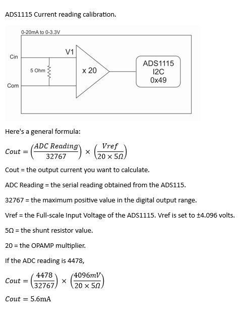
Reading the relevant I2C address of the ADC gives the value of the Analog Input.
Programming Analog Inputs #
#include <Adafruit_ADS1X15.h>
Adafruit_ADS1115 ads2;
#include "Wire.h"
#define SDA 19
#define SCL 20

void setup() {
  Serial.begin(9600);
  Wire.begin(SDA, SCL);
  if (!ads2.begin(0x49)) {
    Serial.println("Failed to initialize ADS 1 .");
  }
  ads2.setGain(GAIN_ONE);
}

void loop() {
  int adc0=0,adc1=0,adc2=0,adc3=0;
  adc0 = ads2.readADC_SingleEnded(0);
  adc1 = ads2.readADC_SingleEnded(1);
  adc2 = ads2.readADC_SingleEnded(2);
  adc3 = ads2.readADC_SingleEnded(3);
  Serial.print("AIN1: ");
  Serial.print(adc0);
  Serial.println(" ");
  Serial.print("AIN2: ");
  Serial.print(adc1);
  Serial.println(" ");
  Serial.print("AIN3: ");
  Serial.print(adc2);
  Serial.println(" ");
  Serial.print("AIN4: ");
  Serial.print(adc3);
  Serial.println(" ");
  Serial.println("-----------------------------------------------------------");
}
RS-485 Communication #
RS 485 Wiring #
| Driver | SP490CN-L |
| UART RX | GPIO48 |
| UART TX | GPIO3 |

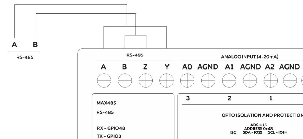
NROVI ESP32 HMI has a 4-wire RS485 connection. So it has terminals A, B, Y, and Z. Connect Y to A and Z to B.
Programming RS-485 #
ESP-HMI series RS-485 connection uses a full-duplex mode of SP490CN-L transmitter with UART
Communication.
#define RXD 48
#define TXD 2
#include "Wire.h"
#define SDA 19
#define SCL 20
void setup() {
  Serial.begin(9600);
  Serial1.begin(9600, SERIAL_8N1, RXD, TXD);
  Wire.begin(SDA, SCL);
}
void loop() {
  Serial1.println("RS485 01 SUCCESS");
  while (Serial1.available()) {
  char c = Serial1.read();
  Serial.write(c);
  }
}
Micro SD Card Support #
| SD CARD CS | GPIO46 |
| MISO | GPIO19 |
| MOSI | GPIO12 |
| SCLK | GPIO13 |
Programming SD Card #
#include "SD.h"
#include <SPI.h>
#define MOSI 13
#define MISO 11
#define SCLK 12
#define CS 10
#include "Wire.h"
#define SDA 19
#define SCL 20
File myFile;
void setup() {
  Serial.begin(9600);
  Wire.begin(SDA, SCL);
  if (!SD.begin(CS)) {
    Serial.println(F("SD CARD FAILED, OR NOT PRESENT!"));
    while (1); // stop the program
  }
  Serial.println(F("SD CARD INITIALIZED."));
  if (!SD.exists("esp32.txt")) {
    Serial.println(F("esp32.txt doesn't exist. Creating esp32.txt file..."));
    // create a new file by opening a new file and immediately close it
    myFile = SD.open("esp32.txt", FILE_WRITE);
    myFile.close();
  }
  if (SD.exists("esp32.txt"))
    Serial.println(F("esp32.txt exists on SD Card."));
  else
    Serial.println(F("esp32.txt doesn't exist on SD Card."));
  }
void loop() {
}
Internal RTC #
| RTC Chip | DS3231 |
| Backup Battery Type | CR2032 |
| Interface | I2C |
| I2C Address | 0x68 |
| SCL Pin | GPIO19 |
| SDA Pin | GPIO20 |
Programming RTC #
#include <Wire.h>
#include "RTClib.h"
#define SDA 19
#define SCL 20
RTC_DS3231 rtc;
void setup() {
   Wire.begin(SDA, SCL);
  Serial.begin(9600);
  rtc.begin();
}
void loop() {
  DateTime now = rtc.now();
  Serial.print(now.year());
  Serial.print("-");
  Serial.print(now.month());
  Serial.print("-");
  Serial.print(now.day());
  Serial.print(" ");
  Serial.print(now.hour());
  Serial.print(":");
  Serial.print(now.minute());
  Serial.print(":");
  Serial.print(now.second());
  Serial.println();
  delay(1000);
}
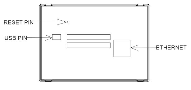
ETHERNET, USB, and Reset #
TFT LED Display #
Programming TFT LED Display #
| Display driver | ER-TFT050-3 |
| Communication | I2C |
| Resolution | 800×480 |
Refer to the GPIO allocation table in the Datasheet for the I2C GPIO of the LED Display.
Getting Started with NORVI ESP32 HMI
LVGL EXAMPLE GUIDE FOR NORVI ESP32 HMI


