
Overview #
The EC-M12-BC-C6-C-A is a compact, battery-powered data logger designed for low-power remote monitoring. Moreover, it combines NB-IoT and LTE-M connectivity with Modbus RTU, enabling reliable industrial data collection. In this guide, we will see how to transmit RS485 Modbus data over MQTT with NORVI Cellular Datalogger
Next, the device transmits RS485 Modbus data from sensors like the XY-MD02, ensuring accurate temperature and humidity readings reach the system for real-time monitoring and efficient industrial operations.
Finally, the device publishes the collected data directly to the ThingsBoard dashboard, enabling seamless IoT integration. Consequently, it enhances industrial monitoring, reduces manual intervention, and maintains continuous low-power operation in remote environments.
Note: For a detailed guide on setting up ThingsBoard, please refer to: Connecting ESP32 to ThingsBoard over WiFi
Initial setup #
A complete introduction to the functionality of EC-M12-BC-C6-C-A is available on EC-M12-BC-C6-C-A User Guide. It is recommended to go through the Guide Guide to get a fundamental understanding on its operation, using the basic functional test code and explore methods of uploading the program to the device.
- First, Set the on-board jumper to position 2 to configure the power source as USB.
When conducting tests on the device, battery capacity can be saved by operating it with the USB Power. Once the testing is complete, the device can be set to battery powered mode.
- To setup the Arduino IDE to program the STM32L0 microcontroller please refer to: EC-M12-BC-C6-C-A User Guide
- You can upload the exported binary file to the STM32 microcontroller using an ST-Link Programmer.
- Connect the GROUND, CLK, DIO, and RESET pins to the ST-Link Programmer.
Hardware setup #
We will be using XY-MD02 Modbus Temperature, Humidity Sensor for the test purpose.
Connect XY-MD02 sensor to 8 pin connector’s RS-485 connections and power the sensor using switchable 12V output as figure 1.
Software setup #
- Define pin configurations as the datasheet.
- Initialize the modem
- Low power begins
- MQTT broker setup
- Enable the RS485 and booster
- Read XY-MD02 sensor data via modbus and send to thingsboard dashboard
- Disable peripherals and booster and go to low power shutdown for 15 minutes.
Please refer below configured GitHub link for the complete program: EC-M12-BC-C6-C-A-Connect_with_Thingsboard
Operating Workflow #
When powered by the battery, the SIM7070 LTE modem connects to the 2G network. After establishing the network and MQTT connections to the ThingsBoard broker, the system reads data from the XY-MD02 Modbus sensor via the RS485 interface and transmits it to the ThingsBoard dashboard.
After the data transmission is complete, the modem is powered down, all peripherals are disconnected, the booster power is disabled, and the MCU enters a low-power shutdown (sleep) mode to conserve energy.
| Stage | Description | Typical Duration |
|---|---|---|
| Wake-up | Device powers up and initializes modem | 1 min |
| Sensor Read | XY-MD02 Modbus read | 10 seconds |
| Data Send | Publish Temperature and Humidity data to ThingsBoard via 2G network | 7 seconds |
| Sleep | Shutdown Mode | 15 minutes |
Power Consumption Analysis #
Power consumption of the system can divide into three main stages
- Initialize the modem and connect to the network.
- Read RS-485 sensor and send data.
- MCU sleep mode (Shutdown mode)
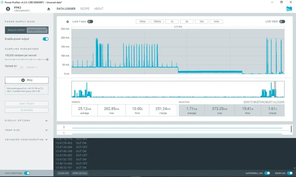
Initialize the modem and connect to network #
During the modem initialization process, the system experiences its highest current consumption. On average, a current of approximately 18.40mA flows for about one minute. The SIM7070 LTE modem connects to the 2G network during this period, drawing several high current spikes reaching up to 0.37A. However, with two lithium batteries in parallel, the system can adequately supply this demand.
A tantalum capacitor (1000 µF) placed close to the modem acts as a local energy reservoir, supplying the instantaneous surge current while the batteries maintain the average load.
According to the ER34615H (D) lithium primary battery datasheet, each cell can deliver a maximum pulse current of 300 mA for 100 milliseconds every 2 minutes. Based on power profile observations, the modem’s initialization phase produces current pulses exceeding 300 mA, lasting 30–40 milliseconds each. These pulses are within the battery’s safe operating capability, allowing the modem to initialize and operate reliably without excessive voltage drop or battery stress.
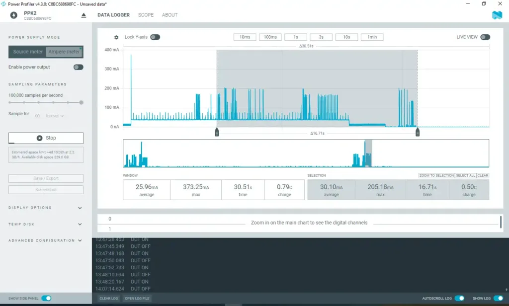
Read RS-485 sensor and send data #
During this process, the system reads data from the XY-MD02 sensor via the RS485 interface and transmits the temperature and humidity readings to ThingsBoard over the 2G network.
At this stage, the system draws an average current of approximately 30.10 mA for a duration of around 17 seconds.
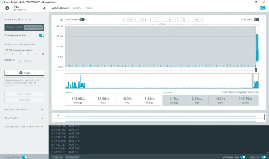
MCU sleep mode (Shutdown mode) #
After data transmission is complete, the MCU enters shutdown mode, during which most peripherals and system clocks are powered down. Only the RTC (Real-Time Clock) remains active to keep track of time.
In this mode, the system draws a very low current of approximately 1.10µA for a duration of 15 minutes. Occasional short current spikes between 2mA and 2.7mA occur due to RTC maintenance activity. These spikes are negligible and do not impact the battery performance, as the lithium battery can safely tolerate up to 300 mA pulse currents for 100 milliseconds, according to its specifications.
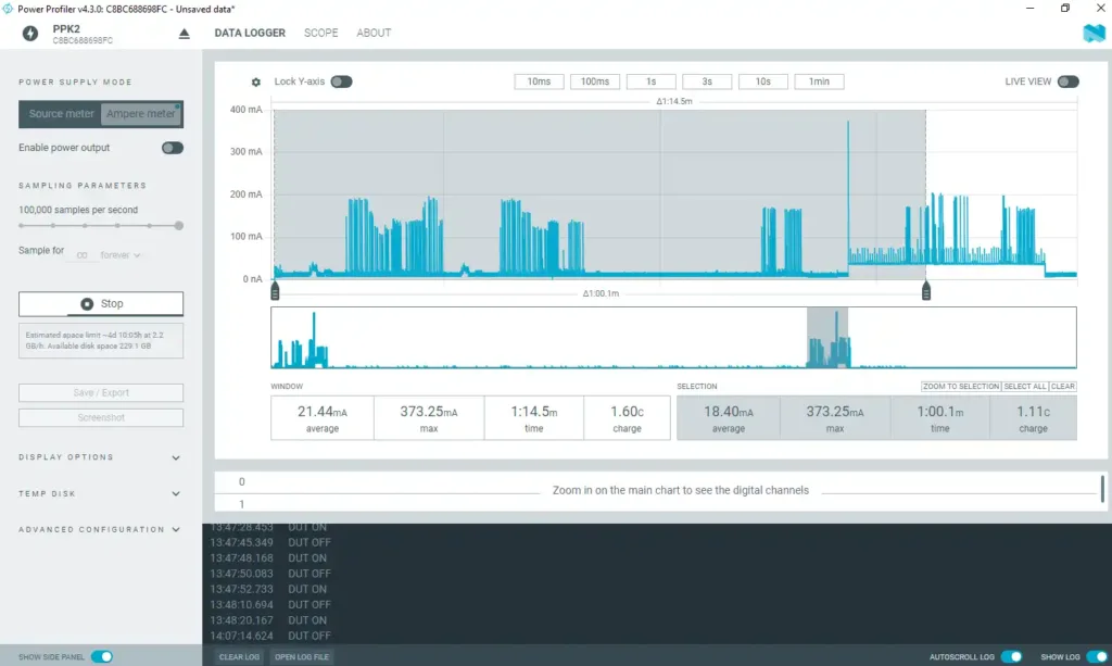
elow figure shows the whole system’s power profile which indicates the average current flow of 1.71mA. It has charge of 1.61c.
| Stage | Mode | Average Current | Duration | Charge | Energy | Max current |
|---|---|---|---|---|---|---|
| Modem initialization | Shutdown | 18.40mA | 1 min | 1.11C | 4.11J | 373mA |
| Data send | Shutdown | 30.10mA | 17 sec | 0.5C | 1.85J | 205mA |
| Sleep (15 min) | Shutdown | 1.10µA | 15 min | 949.59µC | 0.0035J | 2.66mA |
| Send +sleep | Shutdown | 1.71mA | 16.17 min | 1.61C | 5.96J | 373mA |
Battery Life Estimation #
EC0-M12-BC-C6-C-A consists of two 19,000 mAh . So it has total 38,000 mAh battery power. As for the above colleted data we have obtained battery life estimation when data send in every 15 minutes and every 1 hour
| Interval | Average Current per cycle | Estimated life (Hours) | Days | Months | Years |
|---|---|---|---|---|---|
| Every 15 minutes | 1.71mA | 22222.2h | 925.93 days | 30.86 months | 2.54 years |
| Every 1 hour | 402µA | 94527.37h | 3938.64 days | 131.2 months | 10.7 years |
Below shows the formula to calculate average current and battery life for different intervals which help you to estimate the battery life for your application.
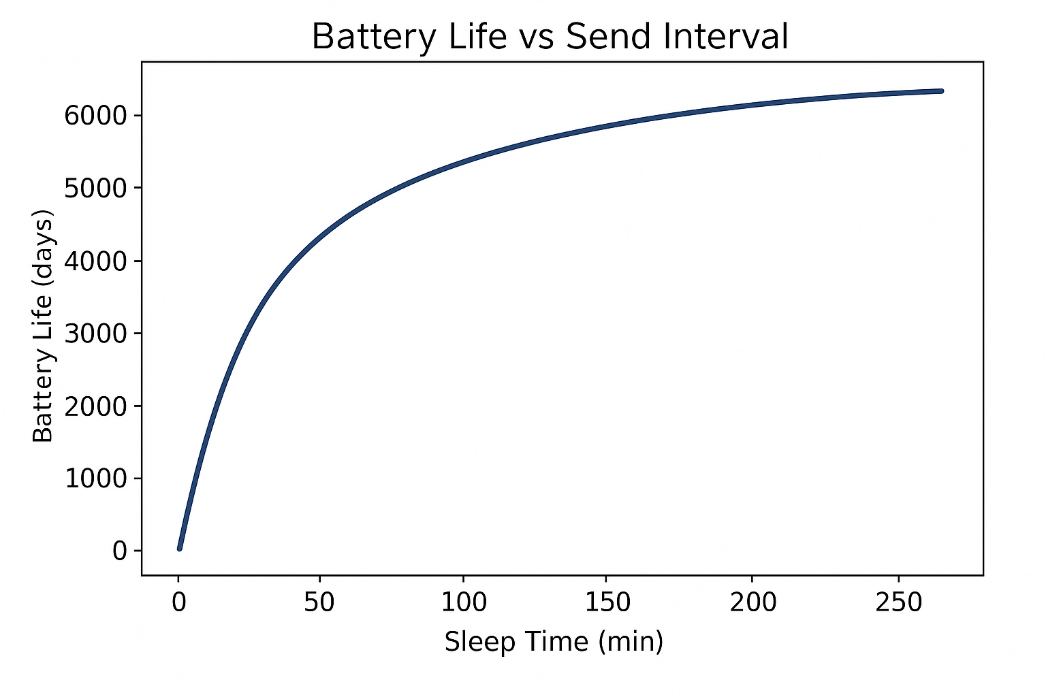
Key Points and Discussion #
Increasing the data transmission interval from 15 minutes to 1 hour extends the battery life by approximately 4.7 times, clearly demonstrating the benefits of optimized duty cycling. By reducing the frequency of data transmissions, the system significantly minimizes power consumption, allowing for substantially longer battery life without compromising functionality.
The XY-MD02 temperature and humidity sensor consumes approximately 1 mA of current. Therefore, the overall battery life of your application will depend on the sensors used. Sensors with higher current consumption will reduce battery life accordingly.
- The STM32 microcontroller supports three types of low-power modes:
- Sleep Mode – Maximum sleep duration: 30–60 seconds.
- In this mode, all peripheral and modem configurations are preserved, and the RAM content remains intact.
- Current consumption is relatively high (20–30 mA), making it unsuitable for multi-minute sleep periods.
- Deep Sleep Mode – Maximum sleep duration: up to 24 hours
- RAM content is retained, but peripherals are paused.
- Typical current consumption is 1–2 mA if the modem is powered.
- For the SIM7070 modem, you can use additional sleep modes to further reduce current consumption. A detailed explanation of this will be provided in a separate article.
- Shutdown Mode – Maximum sleep duration: up to 49 days.
- No RAM or peripheral state is retained. On wake-up, the MCU performs a cold start.
- This mode is the most suitable for long-duration sleep and ultra-low-power applications, as described above.
- Sleep Mode – Maximum sleep duration: 30–60 seconds.
- The cellular signal strength directly affects the power consumption during modem initialization. When the signal strength is below average, the modem requires more current and additional time to connect to the network. Weak signals can also lead to network disconnections, which may result in multiple reconnection attempts, further increasing overall power consumption.


