Product Features #

- Raspberry CM4
- Broadcom BCM2711 quad-core Cortex-A72 (ARM v8) 64-bit SoC
- Integrated 7-inch touch panel.
- PLC functionality
- Ethernet connectivity
- eMMC or micro-SD Card support
- OpenGL ES 3.1, Vulkan 1.0
- Built-in RS-485
- Built-in Digital Inputs
- Analog Inputs
- Transistor Outputs
- DIN-Rail mount

Main #
| Range of Product | Industrial HMI Controller |
| Product Type | Programmable Panel Controller |
| Certifications | EN 61131-2:2007 EN 61010-1:2010+A1:2019 EN IEC 61010-2-201:2018 2014/30/EU- Electromagnetic Compatibility (EMC) Annex III, Part B, Module C |
| Rated supply voltage | 24V DC |
| Communication | WiFI / Bluetooth RS-485 |
| Inputs and Outputs | 8 x Digital Inputs 8 x Analog Inputs 0-10V 7 x Transistor outputs |
| Displays and Visual Indicators | Display |
Complementary #
| Product Unified Code | RPI-PC-AV8-TO7 |
| Product Part Numbers | RPI-PC-AV8-TO7 |
Mechanical Properties #
| Enclosure | OP-360-K |
| Mounting / Installation Method | Top hat type TH35-15 rail conforming to IEC 60715 Top hat type TH35-7.5 rail conforming to IEC 60715 Plate or panel with fixing kit |
| Terminal Type | SCREW TERMINAL |
| Terminal Arrangement | back of the enclosure |
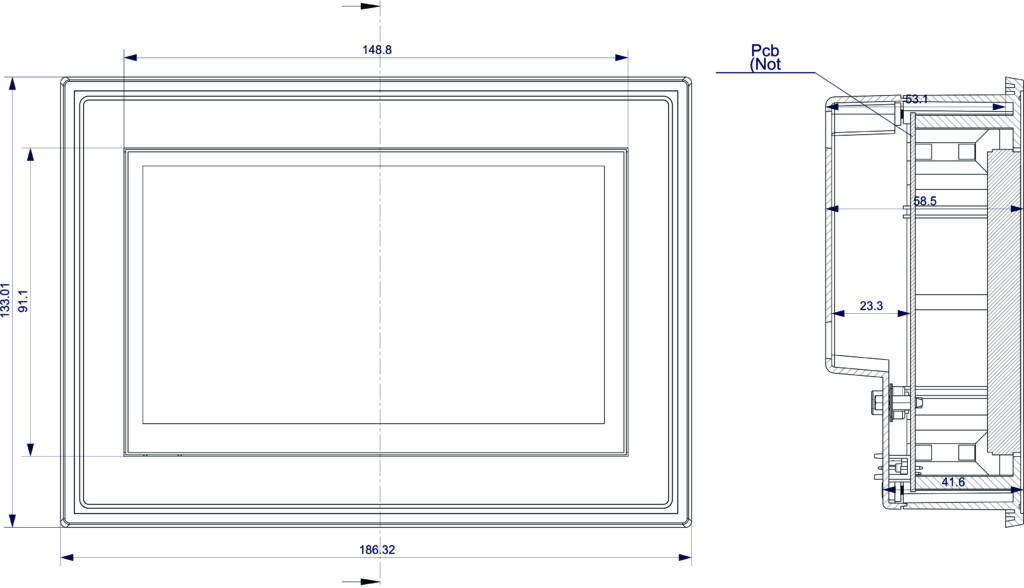
| Length | 149mm |
| Height | 133 mm |
| Width | 59mm |

Environment #
| IP degree of protection | IP20 |
| Operating altitude | 0 – 2000 meters |
| Operating Temperature | – –10 … +85° C (14…185 °F) |
| Storage altitude | 0 – 3000 meters |
| Shock resistance | 15 gn for 11ms |
| Resistance to electrostatic discharge | 4kV on contact 8kV on air |
| Resistance to electromagnetic fields | 10 V/m (80 MHz …… 1GHz) 3 V/m (1.4 MHz …… 2 GHz) 1 V/m (2 MHz …… 3 GHz) |
Electrical Characteristics #
Grid Powered Devices #
| Rated Supply Voltage (V) | 24V DC |
| Current Consumption (mA) | 100mA |
| Recommended Power Source | 2W |
Processing #
| SOC / MCU | Raspberry Pi Compute Model 4 |
| storage controller | eMMC or SD card |
| Flash Memory | 8GB, 16GB, or 32GB eMMC |
| RAM | up to 8GB |
| SDRAM | 1GB, 2GB, 4GB or 8GB LPDDR4-3200 |
Peripherals #
microSD Cards support #
The micro SD Card socket is a PUSH-PUSH socket.
To release the micro SD Card a gentle push on the micro SD Card will enable it to be removed.
| SD_DAT0 | CM4 pin 63 |
| SD_DAT1 | CM4 pin 67 |
| SD_DAT2 | CM4 pin 69 |
| SD_DAT3 | CM4 pin 61 |
| SD_CLK | CM4 pin 57 |
| SD_CMD | CM4 pin 62 |
Internal RTC #
| RTC Chip | DS3231 |
| Backup Battery Type | CR2032 |
| Interface | I2C |
| SCL Pin | GPIO4 |
| SDA Pin | GPIO44 |
HDMI Display and Touch Panel #
The CM4 supports two display ports, DISP0(2 lanes) and DISP1(4 lanes). Each lane supports a maximum data rate per lane of 1Gbit/s.
| Display Interface | HDMI |
| Display Size | 7 inch |
| Resolution | 1024×600 |
| Display Panel | IPS screen |
| Touch Screen Type | Capacitive Touch Screen |
| SCL Pin | IO45 |
| SDA Pin | IO44 |
INPUTS and OUTPUTS #
Digital Inputs #
| Number of Digital Inputs | 8 |
| Digital Input Polarity | Sink and Source |
| Digital Input Maximum Voltage | 32V DC |
| Digital Input Minimum Voltage | 18V DC |
| Maximum Switching Frequency | 1 kHz |
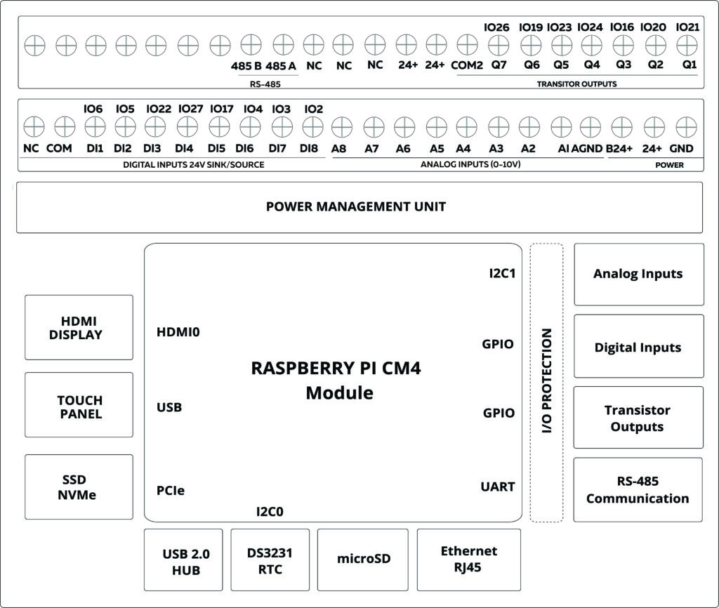
| Terminal Arrangement | Digital Input 1 – IO6 Digital Input 2 – IO5 Digital Input 3 – IO33 Digital Input 4 – IO27 Digital Input 5 – IO17 Digital Input 6 – IO4 Digital Input 7 – IO3 Digital Input 8 – IO2  |
Analog Inputs #
| Number of Analog Inputs | 8 |
| Analog Input Measurement Range | 0-10V |
| Analog Input Maximum Voltage | 38V DC |
| Analog to Digital Converter (ADC) Address | 0x48,0x49 |
| Terminal Arrangement | A1 : Analog Input 1 – 0x49 – AIN0 A2 : Analog Input 2 – 0x49 – AIN1 A3 : Analog Input 3 – 0x49 – AIN2 A4 : Analog Input 4 – 0x49 – AIN3 A5 : Analog Input 5 – 0x48 – AIN0 A6 : Analog Input 6 – 0x48 – AIN1 A7 : Analog Input 7 – 0x48 – AIN2 A8 : Analog Input 8 – 0x48 – AIN3 |
Transistor Outputs #
| Number of Transistor Outputs | 7 |
| Transistor Output Type | OPEN COLLECTOR |
| Maximum Sink/Source Current (mA) | 100mA |
| Maximum Applicable Voltage | 40V DC |
| Maximum Switching Frequency | 1 kHz |
| Terminal Arrangement | Q1 – Transistor Output 1 – IO21 Q2 – Transistor Output 2 – IO20 Q3 – Transistor Output 3 – IO16 Q4 – Transistor Output 4 – IO24 Q5 – Transistor Output 5 – IO23 Q6 – Transistor Output 6 – IO19 Q7 – Transistor Output 7 – IO26 |
Communication Channels #
RS-485 Communication #
| Communication Mode | HALF DUPLEX |
| Transceiver | SP490CN-L |
| Unit Load | 1 |
| TX Pin | GPIO15 |
| RX Pin | GPIO14 |
| Flow Control | GPIO18 |
| Communication Mode | Via UART |
| Terminal Arrangement |
Ethernet #
Gigabit Ethernet transceiver IEEE 1588-2008 compliant MDI crossover, Pair skew, and pair polarity correction.
USB Device #
Designed to enable the CM4 to be updated via RPI boot. When a USB cable is plugged in the USB hub is automatically disabled, so the CM4 USB 2.0 port becomes a USB device
USB 2.0 HUB #
The device has an onboard USB 2.0 hub. Can be used to connect third-party USB Devices like USB Modems and data converters.
This connects to the CM4 USB 2.0 port. Two ports from the hub are connected to a connector. The other port of the USB 2.0 hub is connected to the touch screen.
There is an internal current limit switch to provide VBUS to the USB connectors. The current limit is set to approximately 1.2A.
The USB interface is disabled to save power by default on the CM4. To enable it you need to add the following to the config.txt file: dtoverlay=dwc2,dr_mode=host *
The factory version of the Raspbian OS which is pre-installed on the device has a USB 2.0 hub enabled by default.
M.2 NVMe Storage (Internal Port) #
M.2 NVMe Storage can be installed as additional storage for the controller, where heavy applications are run, NVMe boot is not supported by the boot loader, the device must boot from a separate source.
Supported Programming Methods #
Python
Node-RED
Factory Installed OS #
Raspbian OS Full Pre-configured for DS3231 RTC
USB2.0 HUB
Disabled Display Sleep
Ordering Information #
| P/N | Model Code | CPU | RAM | WiFi | eMMC |
| RPI-PC-AV8-TO7-G1 | CPU G1 | 64-bit SoC @ 1.5GHz | 2GB | Yes | – |
| RPI-PC-AV8-TO7-G2 | CPU G2 | 2GB | Yes | 8 | |
| RPI-PC-AV8-TO7-G3 | CPU G3 | 2GB | Yes | 16 | |
| RPI-PC-AV8-TO7-G4 | CPU G4 | 4GB | Yes | 32 |
GPIO Map #
| GPIO | Description | Usage |
| 0 | ||
| 1 | ||
| 2 | Input | Digital Input 8 |
| 3 | Input | Digital Input 7 |
| 4 | Input | Digital Input 6 |
| 5 | Input | Digital Input 2 |
| 6 | Input | Digital Input 1 |
| 14 | RS485 | RX |
| 15 | RS485 | TX |
| 16 | output | Transistor output 3 |
| 17 | Input | Digital Input 5 |
| 18 | RS485 | FC |
| 19 | output | Transistor output 1 |
| 20 | output | Transistor output 5 |
| 21 | output | Transistor output 6 |
| 22 | Input | Digital Input 3 |
| 23 | output | Transistor output 3 |
| 24 | output | Transistor output 4 |
| 25 | ||
| 26 | output | Transistor output 2 |
| 27 | Input | Digital Input 4 |
| 33 | ||
| 44 | SDA | |
| 45 | SCL |


