
The NORVI X-UARTIO is a versatile communication expansion module for the NORVI X modular controller platform. It provides multiple serial communication interfaces including RS485, RS232, and UART, enabling flexible connectivity to industrial devices, sensors, meters, and peripherals.
The module uses shared MCU I/O lines with intelligent switching, allowing multiple physical ports to be supported while minimizing processor pin usage. Interface selection is fully controlled via firmware.
Product Features #
- 2 × RS485 communication ports
- 2 × RS232 communication ports
- 4 × UART ports (multiplexed)
- Industrial-grade RS485 and RS232 transceivers
- Flexible I/O routing via GPIO- and CS-controlled switching
- UART pins usable as GPIO when not configured for UART
- Designed for NORVI X expansion architecture
System Architecture #
- RS485: Half-duplex differential communication
- RS232: Full-duplex serial communication
- UART (TTL level): Direct MCU UART / GPIO connectivity
Applications #
- Industrial automation and control systems
- Modbus RTU and serial fieldbus communication
- Sensor and meter integration
- Legacy device connectivity via RS232
- Multi-device UART expansion
- OEM and system integrator solutions
Product Block Diagram #
Main #
| Range of Product | NORVI X |
| Product type | Expansion Module for NORVI X Series |
| Certifications | EN 61131-2:2007 EN 61010-1:2010+A1:2019 EN IEC 61010-2-201:2018 2014/30/EU- Electromagnetic Compatibility (EMC) Annex III, Part B, Module C |
| Rated supply voltage | 24V DC |
Complementary #
| Product Part Numbers | NORVI X-RTD4 |
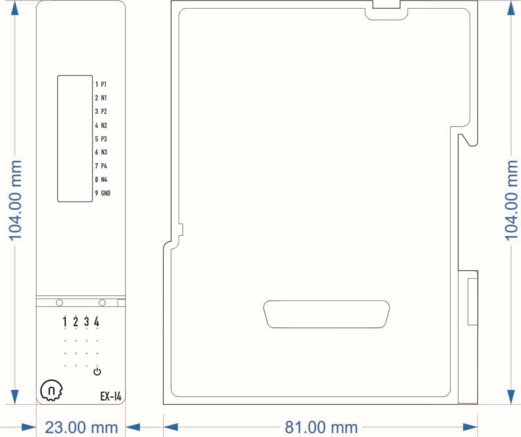
Mechanical Properties #
| Enclosure | NORVI X-N1 |
| Mounting / Installation Method | DIN RAIL |
| Terminal Type | Push-in terminal |
| Terminal Arrangement | Front |
| Length | 81.00 mm |
| Height | 104.00 mm |
| Width | 23.00 mm |
Environment #
| IP degree of protection | IP20 |
| Operating altitude | 0 – 2000 meters |
| Operating Temperature | –10 … +85° C (14…185 °F) |
| Storage altitude | 0 – 3000 meters |
| Shock resistance | 15 gn for 11ms |
| Resistance to electrostatic discharge | 4kV on contact 8kV on air |
| Resistance to electromagnetic fields | 10 V/m (80 MHz …… 1GHz) 3 V/m (1.4 MHz …… 2 GHz) 1 V/m (2 MHz …… 3 GHz) |
Electrical Characteristics #
Grid Powered Devices #
| Rated Supply Voltage (V) | 24V DC |
| Current Consumption (mA) | 80mA @ 24VDC |
I/O Specifications #
| Parameter | Specification |
|---|---|
| RS485 Channels | 1 (Selectable) |
| RS232 Channels | 1 (Selectable) |
| UART Channels | 2 (Multiplexed) |
| RS485 Transceiver | SN65HVD72DGKR |
| UART Logic Level | TTL |
| Power Supply | Supplied via NORVI X expansion bus |
| Communication Bus | Internal Expansion Bus |
| Connector Type | Push-in Terminal Block |
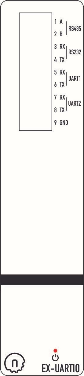
Terminal Configuration #
| No. | Terminal | Description |
|---|---|---|
| 1 | RS485-A | RS485 Channel – A |
| 2 | RS485-B | RS485 Channel – B |
| 3 | RS232-RX | RS232 Channel – RX |
| 4 | RS232-TX | RS232 Channel – TX |
| 5 | UART-1RX | UART Channel 1 – RX |
| 6 | UART-1TX | UART Channel 1 – TX |
| 7 | UART-2RX | UART Channel 2 – RX |
| 8 | UART-2TX | UART Channel 2 – TX |
| 9 | GND | Ground |
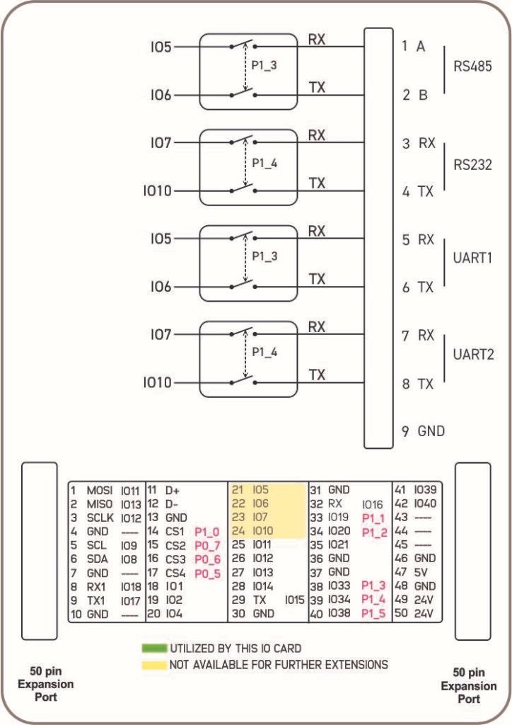
GPIO Utilization #
RS485 Interface
- RX: IO5
- TX: IO6
- Channel Select: P1_3 – Expanded IO from CPU
- Active Channel: RS485
RS232 Interface
- RX: IO7
- TX: IO10
- Channel Select: P1_4 – Expanded IO from CPU
- Active Channel: RS232
UART 1
- RX: IO5
- TX: IO6
- Channel Select: P1_3 – Expanded IO from CPU – Refer CPU Datasheet
UART 2
- RX: IO7
- TX: IO10
- Channel Select: P1_4 – Expanded IO from CPU – Refer CPU Datasheet
Expansion Port #
Utilized GPIO Connections are highlighted in Yellow. They cannot be used for any other purpose with this module connected.
| PIN INDEX | Purpose | GPIO | SOURCE |
|---|---|---|---|
| 1 | MOSI | IO11 | ESP32-S3 |
| 2 | MISO | IO13 | |
| 3 | SCLK | IO12 | |
| 4 | GND | —- | |
| 5 | SCL | IO9 | |
| 6 | SDA | IO8 | |
| 7 | GND | —- | |
| 8 | RX1 | IO18 | |
| 9 | TX1 | IO17 | |
| 10 | GND | —- | |
| 11 | D+ | —- | |
| 12 | D- | —- | |
| 13 | GND | —- | |
| 14 | CS1 | P1_0 | PCA9539 I2C Address 0x75 |
| 15 | CS2 | P0_7 | |
| 16 | CS3 | P0_6 | |
| 17 | CS4 | P0_5 | |
| 18 | IO1 | IO1 | ESP32-S3 |
| 19 | IO2 | IO2 | |
| 20 | IO4 | IO4 | |
| 21 | IO5 | IO5 | |
| 22 | IO6 | IO6 | |
| 23 | IO7 | IO7 | |
| 24 | IO10 | IO10 | |
| 25 | IO11 | IO35 | |
| 26 | IO12 | IO36 | |
| 27 | IO13 | IO37 | |
| 28 | IO14 | IO14 | |
| 29 | RS485_TX | IO15 | |
| 30 | GND | —- | |
| 31 | GND | —- | |
| 32 | RS485_RX | IO16 | |
| 33 | P1_1 | P1_1 | PCA9539 I2C Address 0x75 |
| 34 | P1_2 | P1_2 | |
| 35 | IO21 | IO21 | ESP32-S3 |
| 36 | GND | —- | |
| 37 | GND | —- | |
| 38 | P1_3 | P1_3 | PCA9539 I2C Address 0x75 |
| 39 | P1_4 | P1_4 | |
| 40 | P1_5 | P1_5 | |
| 41 | IO39 | IO39 | ESP32-S3 |
| 42 | IO40 | IO40 | |
| 43 | NC | —- | |
| 44 | NC | —- | |
| 45 | NC | —- | |
| 46 | GND | —- | |
| 47 | 5V | 5V | Power |
| 48 | GND | GND | |
| 49 | 24V | 24V | |
| 50 | 24V | 24V |


