
The NORVI X-RTD4 is a high-precision 4-channel RTD expansion module for the NORVI X modular controller platform. It utilizes the 15-bit ADC to provide laboratory-grade temperature digitization for Platinum RTDs.
The module features an integrated analog multiplexer and an onboard STM32 MCU, allowing for sequential monitoring of four independent sensors while offloading processing from the main controller.
Product Features #
- High-Precision ADC Integrated 15-bit RTD-to-Digital converter
- 4-Channel Input Sequential monitoring
- Flexible Wiring
- Automatic Fault Detection
- 4-Way DIP Switch
- Status LED indicators for each input channel
- Plug-and-play connection to NORVI X CPU module via expansion bus
- DIN-rail Mounting
Applications #
- Industrial automation and control systems
- HVAC and Building Automation
- Medical and Laboratory Equipment
- Energy and Power Systems
- Environmental Data Logging
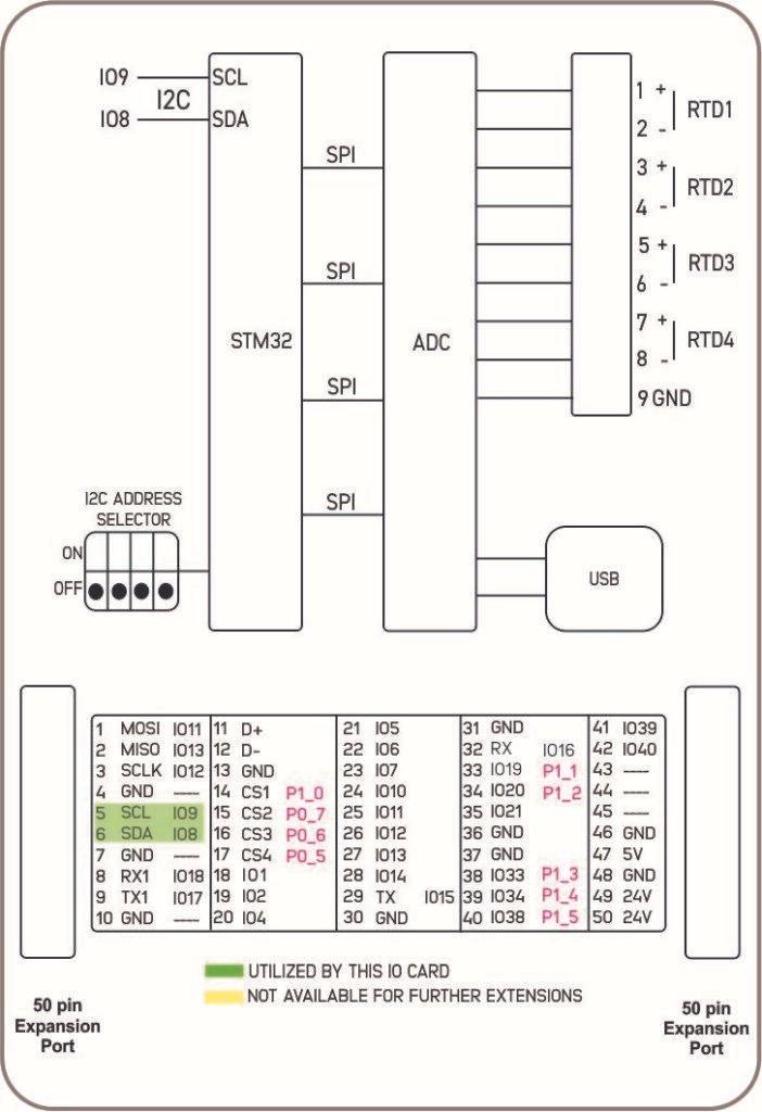
Product Block Diagram #
Main #
| Range of Product | NORVI X |
| Product type | Expansion Module for NORVI X Series |
| Certifications | EN 61131-2:2007 EN 61010-1:2010+A1:2019 EN IEC 61010-2-201:2018 2014/30/EU- Electromagnetic Compatibility (EMC) Annex III, Part B, Module C |
| Rated supply voltage | 24V DC |
Complementary #
| Product Part Numbers | NORVI X-RTD4 |
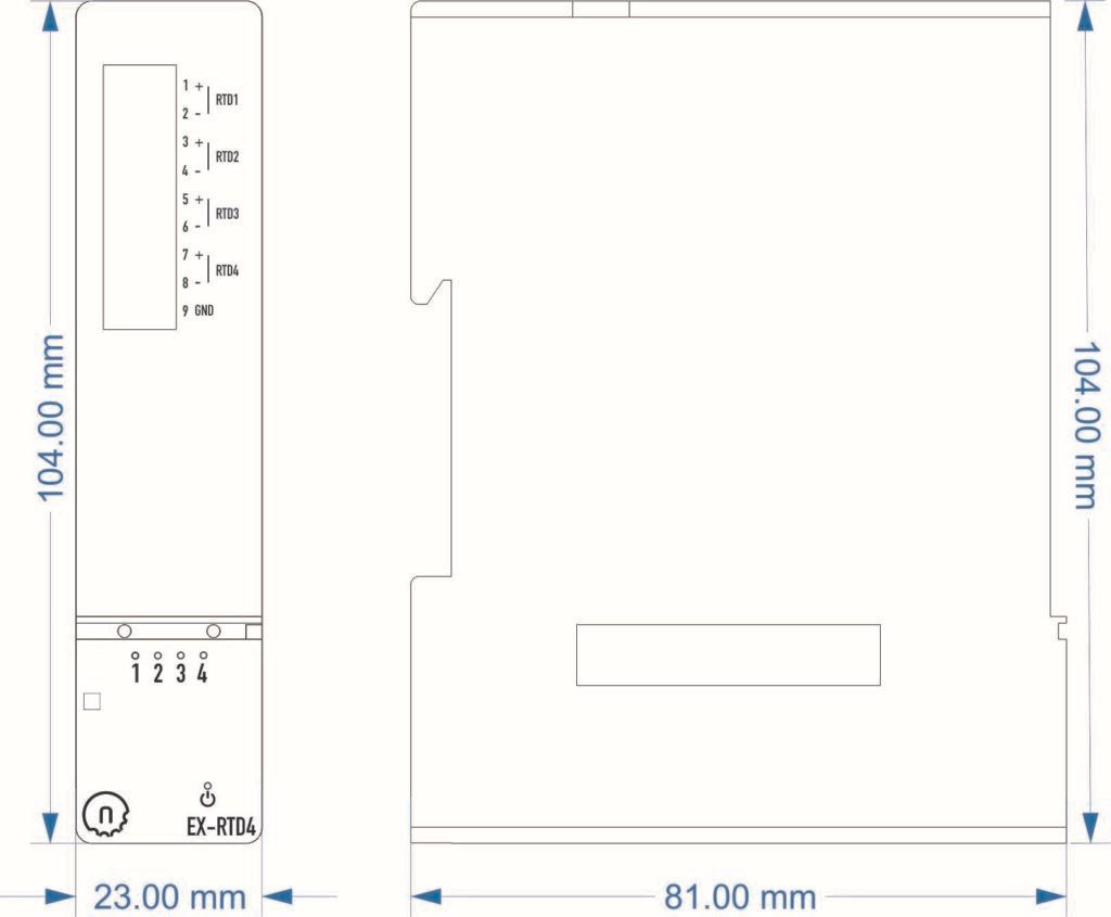
Mechanical Properties #
| Enclosure | NORVI X-N1 |
| Mounting / Installation Method | DIN RAIL |
| Terminal Type | Push-in terminal |
| Terminal Arrangement | Front |
| Length | 81.00 mm |
| Height | 104.00 mm |
| Width | 23.00 mm |
Environment #
| IP degree of protection | IP20 |
| Operating altitude | 0 – 2000 meters |
| Operating Temperature | –10 … +85° C (14…185 °F) |
| Storage altitude | 0 – 3000 meters |
| Shock resistance | 15 gn for 11ms |
| Resistance to electrostatic discharge | 4kV on contact 8kV on air |
| Resistance to electromagnetic fields | 10 V/m (80 MHz …… 1GHz) 3 V/m (1.4 MHz …… 2 GHz) 1 V/m (2 MHz …… 3 GHz) |
Electrical Characteristics #
Grid Powered Devices #
| Rated Supply Voltage (V) | 24V DC |
| Current Consumption (mA) | 80mA @ 24VDC |
I/O Specifications #
| Parameter | Specification |
|---|---|
| Input Channels | 4 Independent RTD Channels |
| Resolution | 15-bit |
| Debug Interface | Micro-USB (For Debugging & Firmware Only) |
| Communication | SPI / I2C via Expansion Bus |
| Microcontroller | STM32 Series (Internal Bridge) |
| Power Supply | 24V DC (via Expansion Bus) |
| Internal Interface | High-Speed SPI (MCU to ADC Output Stage) |
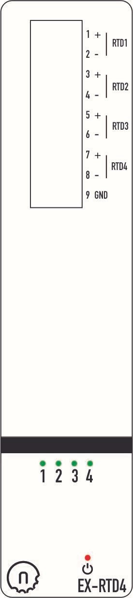
Terminal Configuration #
| No. | Terminal | Description |
|---|---|---|
| 1 | RTD1+ | Positive Input – Channel 1 |
| 2 | RTD1− | Negative Input – Channel 1 |
| 3 | RTD2+ | Positive Input – Channel 2 |
| 4 | RTD2− | Negative Input – Channel 2 |
| 5 | RTD3+ | Positive Input – Channel 3 |
| 6 | RTD3− | Negative Input – Channel 3 |
| 7 | RTD4+ | Positive Input – Channel 4 |
| 8 | RTD4− | Negative Input – Channel 4 |
| 9 | GND | Ground |
GPIO Utilization #
| Utilization | Connection to CPU |
|---|---|
| SCL | IO9 |
| SDA | IO8 |
I2C Address Selection #
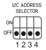
| DIP 1 | DIP 2 | DIP 3 | DIP 4 | Address |
|---|---|---|---|---|
| OFF | OFF | OFF | OFF | 0x00 |
| OFF | OFF | OFF | ON | 0x01 |
| OFF | OFF | ON | OFF | 0x02 |
| OFF | OFF | ON | ON | 0x03 |
| OFF | ON | OFF | OFF | 0x04 |
| OFF | ON | OFF | ON | 0x05 |
| OFF | ON | ON | OFF | 0x06 |
| OFF | ON | ON | ON | 0x07 |
| ON | OFF | OFF | OFF | 0x08 |
| ON | OFF | OFF | ON | 0x09 |
| ON | OFF | ON | OFF | 0x0A |
| ON | OFF | ON | ON | 0x0B |
Expansion Port #
Utilized GPIO Connections are highlighted in Green. They cannot be used for any other purpose with this module connected.
| PIN INDEX | Purpose | GPIO | SOURCE |
|---|---|---|---|
| 1 | MOSI | IO11 | ESP32-S3 |
| 2 | MISO | IO13 | |
| 3 | SCLK | IO12 | |
| 4 | GND | —- | |
| 5 | SCL | IO9 | |
| 6 | SDA | IO8 | |
| 7 | GND | —- | |
| 8 | RX1 | IO18 | |
| 9 | TX1 | IO17 | |
| 10 | GND | —- | |
| 11 | D+ | —- | |
| 12 | D- | —- | |
| 13 | GND | —- | |
| 14 | CS1 | P1_0 | PCA9539 I2C Address 0x75 |
| 15 | CS2 | P0_7 | |
| 16 | CS3 | P0_6 | |
| 17 | CS4 | P0_5 | |
| 18 | IO1 | IO1 | ESP32-S3 |
| 19 | IO2 | IO2 | |
| 20 | IO4 | IO4 | |
| 21 | IO5 | IO5 | |
| 22 | IO6 | IO6 | |
| 23 | IO7 | IO7 | |
| 24 | IO10 | IO10 | |
| 25 | IO11 | IO35 | |
| 26 | IO12 | IO36 | |
| 27 | IO13 | IO37 | |
| 28 | IO14 | IO14 | |
| 29 | RS485_TX | IO15 | |
| 30 | GND | —- | |
| 31 | GND | —- | |
| 32 | RS485_RX | IO16 | |
| 33 | P1_1 | P1_1 | PCA9539 I2C Address 0x75 |
| 34 | P1_2 | P1_2 | |
| 35 | IO21 | IO21 | ESP32-S3 |
| 36 | GND | —- | |
| 37 | GND | —- | |
| 38 | P1_3 | P1_3 | PCA9539 I2C Address 0x75 |
| 39 | P1_4 | P1_4 | |
| 40 | P1_5 | P1_5 | |
| 41 | IO39 | IO39 | ESP32-S3 |
| 42 | IO40 | IO40 | |
| 43 | NC | —- | |
| 44 | NC | —- | |
| 45 | NC | —- | |
| 46 | GND | —- | |
| 47 | 5V | 5V | Power |
| 48 | GND | GND | |
| 49 | 24V | 24V | |
| 50 | 24V | 24V |


