The NORVI X-Q16 is a 16 x Transistor Outputs Expansion module designed for the NORVI X modular controller platform.
It provides sixteen high-side switching channels suitable for driving industrial actuators, relays, and solenoids. The outputs are optically isolated for circuit protection and utilize high-side MOSFET switches, enabling reliable control of DC loads with integrated fuse protection for industrial safety.
Product Features #
- 16 × Transistor Output channels
- High-side switching (up to 24V DC)
- Full optical isolation for circuit protection
- Enhanced Circuit Protection
- Dual Opto-Isolation
- Integrated fuse and surge protection per channel
- Individual LED status indicators
- Designed for NORVI X modular architecture
Applications #
- High-Density Actuator Control
- Complex Signal Management
- Industrial Automation
- High-Density PLC Output Expansion
- Remote Multi-Device Power Management
- Complex Relay and Contactor Logic Switching
- Large LED Matrix/Indicator Arrays
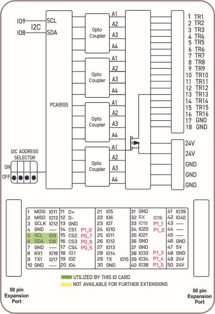
Product Block Diagram #
| Range of Product | NORVI X |
| Product type | Expansion Module for NORVI X Series |
| Certifications | EN 61131-2:2007 EN 61010-1:2010+A1:2019 EN IEC 61010-2-201:2018 2014/30/EU- Electromagnetic Compatibility (EMC) Annex III, Part B, Module C |
| Rated supply voltage | 24V DC |
Complementary #
| Product Part Numbers | NORVI X-Q16 |
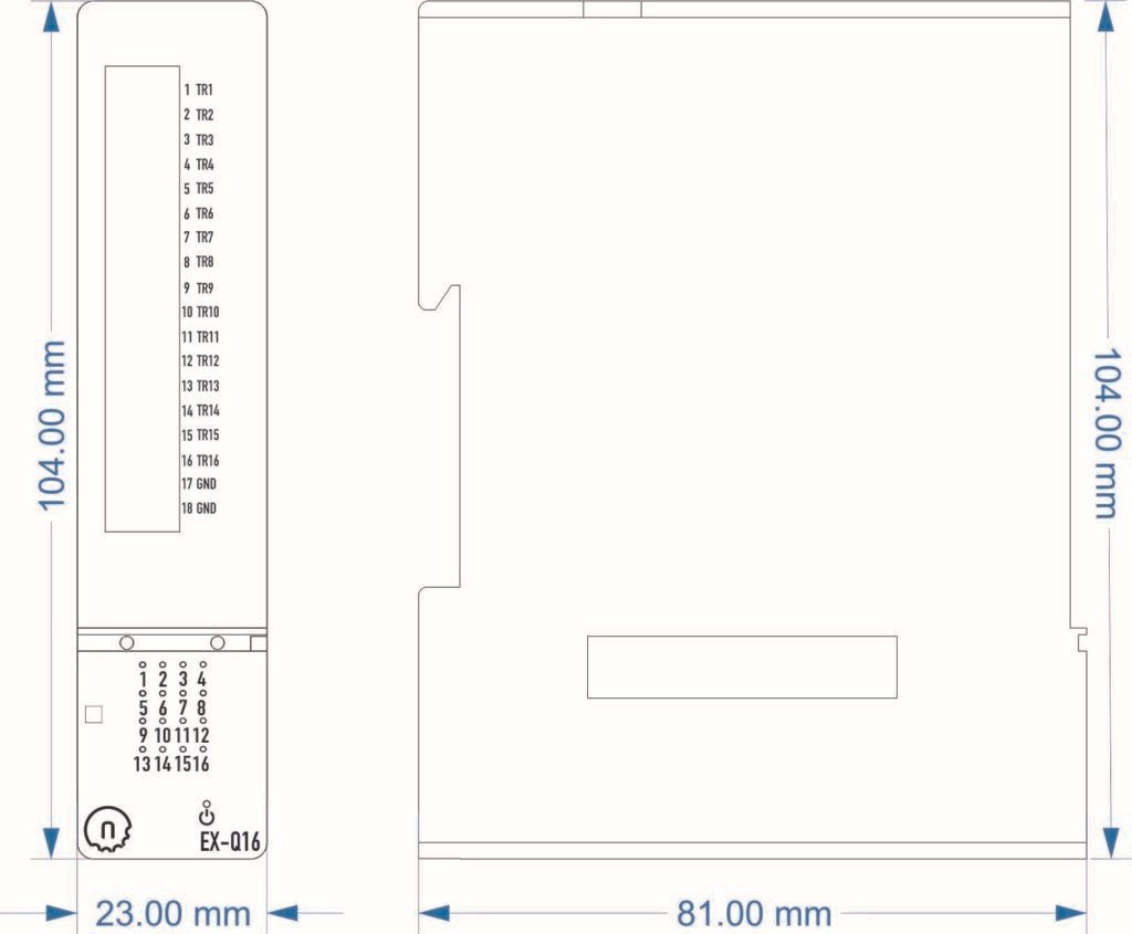
Mechanical Properties #
| Enclosure | NORVI X-N1 |
| Mounting / Installation Method | DIN RAIL |
| Terminal Type | Push-in terminal |
| Terminal Arrangement | Front |
| Length | 81.00 mm |
| Height | 104.00 mm |
| Width | 23.00 mm |
Environment #
| IP degree of protection | IP20 |
| Operating altitude | 0 – 2000 meters |
| Operating Temperature | –10 … +85° C (14…185 °F) |
| Storage altitude | 0 – 3000 meters |
| Shock resistance | 15 gn for 11ms |
| Resistance to electrostatic discharge | 4kV on contact 8kV on air |
| Resistance to electromagnetic fields | 10 V/m (80 MHz …… 1GHz) 3 V/m (1.4 MHz …… 2 GHz) 1 V/m (2 MHz …… 3 GHz) |
Electrical Characteristics #
Grid Powered Devices
| Rated Supply Voltage (V) | 24V DC |
| Current Consumption (mA) | 80mA @ 24VDC |
I/O Specifications #
| Parameter | Specification |
|---|---|
| Number of Outputs | 16 Transistor Output Channels |
| Output Type | High-Side Switch |
| Switching Transistor | P-Channel MOSFET |
| Isolation Type | Optocoupler Isolation |
| Operating Voltage | 24V DC Nominal |
| Protection (Per Channel) | Per-channel resettable PTC fuse |
| Switching Frequency | High-Speed |
| Output Diagnostics | Individual LED indicators |
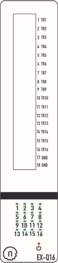
| Field Connector | 18-Pin Terminal Block |
Terminal Configuration #
| No. | Terminal | Description |
|---|---|---|
| 1 | TR1 | Transistor Output 1 |
| 2 | TR2 | Transistor Output 2 |
| 3 | TR3 | Transistor Output 3 |
| 4 | TR4 | Transistor Output 4 |
| 5 | TR5 | Transistor Output 5 |
| 6 | TR6 | Transistor Output 6 |
| 7 | TR7 | Transistor Output 7 |
| 8 | TR8 | Transistor Output 8 |
| 9 | TR9 | Transistor Output 9 |
| 10 | TR10 | Transistor Output 10 |
| 11 | TR11 | Transistor Output 11 |
| 12 | TR12 | Transistor Output 12 |
| 13 | TR13 | Transistor Output 13 |
| 14 | TR14 | Transistor Output 14 |
| 15 | TR15 | Transistor Output 15 |
| 16 | TR16 | Transistor Output 16 |
| 17 | GND | Ground |
| 18 | GND | Ground |
GPIO Utilization #
| Utilization | Connection to CPU |
|---|---|
| SCL | IO9 |
| SDA | IO8 |
I2C Address Selection #
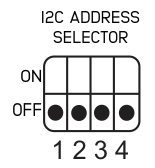
| DIP 3 | DIP 2 | DIP 1 | Address |
|---|---|---|---|
| OFF | OFF | OFF | 0x27 |
| OFF | OFF | ON | 0x26 |
| OFF | ON | OFF | 0x25 |
| OFF | ON | ON | 0x24 |
| ON | OFF | OFF | 0x23 |
| ON | OFF | ON | 0x22 |
| ON | ON | OFF | 0x21 |
| ON | ON | ON | 0x20 |
Expansion Port #
Utilized GPIO Connections are highlighted in Green. They cannot be used for any other purpose with this module connected.
| PIN INDEX | Purpose | GPIO | SOURCE |
|---|---|---|---|
| 1 | MOSI | IO11 | ESP32-S3 |
| 2 | MISO | IO13 | |
| 3 | SCLK | IO12 | |
| 4 | GND | —- | |
| 5 | SCL | IO9 | |
| 6 | SDA | IO8 | |
| 7 | GND | —- | |
| 8 | RX1 | IO18 | |
| 9 | TX1 | IO17 | |
| 10 | GND | —- | |
| 11 | D+ | —- | |
| 12 | D- | —- | |
| 13 | GND | —- | |
| 14 | CS1 | P1_0 | PCA9539 I2C Address 0x75 |
| 15 | CS2 | P0_7 | |
| 16 | CS3 | P0_6 | |
| 17 | CS4 | P0_5 | |
| 18 | IO1 | IO1 | ESP32-S3 |
| 19 | IO2 | IO2 | |
| 20 | IO4 | IO4 | |
| 21 | IO5 | IO5 | |
| 22 | IO6 | IO6 | |
| 23 | IO7 | IO7 | |
| 24 | IO10 | IO10 | |
| 25 | IO11 | IO35 | |
| 26 | IO12 | IO36 | |
| 27 | IO13 | IO37 | |
| 28 | IO14 | IO14 | |
| 29 | RS485_TX | IO15 | |
| 30 | GND | —- | |
| 31 | GND | —- | |
| 32 | RS485_RX | IO16 | |
| 33 | P1_1 | P1_1 | PCA9539 I2C Address 0x75 |
| 34 | P1_2 | P1_2 | |
| 35 | IO21 | IO21 | ESP32-S3 |
| 36 | GND | —- | |
| 37 | GND | —- | |
| 38 | P1_3 | P1_3 | PCA9539 I2C Address 0x75 |
| 39 | P1_4 | P1_4 | |
| 40 | P1_5 | P1_5 | |
| 41 | IO39 | IO39 | ESP32-S3 |
| 42 | IO40 | IO40 | |
| 43 | NC | —- | |
| 44 | NC | —- | |
| 45 | NC | —- | |
| 46 | GND | —- | |
| 47 | 5V | 5V | Power |
| 48 | GND | GND | |
| 49 | 24V | 24V | |
| 50 | 24V | 24V |


