
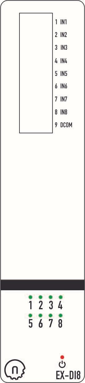
The NORVI X-DI8 is an 8-channel digital input expansion module for the NORVI X Modular Controller. It provides protected 24 V DC digital inputs for industrial switches, sensors, and logic-level signals.
At its core, the module integrates a PCA9538 I²C port expander, allowing the NORVI X CPU to read input states efficiently via the internal expansion bus. With four selectable I²C addresses, up to four DI8 modules can be connected on the same bus, providing a total of 32 digital inputs per controller.
Designed for modular scalability and DIN-rail installation, the NORVI X-DI8 ensures reliable, noise-immune, and space-efficient input expansion for industrial and automation systems.
Product Features #
- 8 × Optically isolated 24 V DC digital inputs
- Bi-directional optocouplers — support both sourcing (PNP) and sinking (NPN) inputs
- One common terminal for all eight inputs
- PCA9538 I²C port expander with 4 selectable addresses
- Up to 4 DI8 modules per controller (32 inputs max)
- Built-in over-voltage and reverse-polarity protection
- Status LED indicators for each input channel
- Plug-and-play connection to NORVI X CPU module via expansion bus
- DIN-rail mountable industrial enclosure
Applications #
- Machine and process signal monitoring
- PLC and control system I/O expansion
- Sensor interfacing in industrial automation
- Low-frequency pulse and state detection
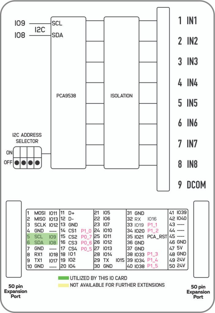
Product Block Diagram #
Main #
| Range of Product | NORVI X |
| Product type | Expansion Module for NORVI X Series |
| Certifications | EN 61131-2:2007 EN 61010-1:2010+A1:2019 EN IEC 61010-2-201:2018 2014/30/EU- Electromagnetic Compatibility (EMC) Annex III, Part B, Module C |
| Rated supply voltage | 24V DC |
Complementary #
| Product Part Numbers | NORVI X-DI8 |
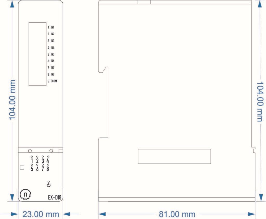
Mechanical Properties #
| Enclosure | NORVI X-N1 |
| Mounting / Installation Method | DIN RAIL |
| Terminal Type | Push-in terminal |
| Terminal Arrangement | Front |
| Length | 81.00 mm |
| Height | 104.00 mm |
| Width | 23.00 mm |
Environment #
| IP degree of protection | IP20 |
| Operating altitude | 0 – 2000 meters |
| Operating Temperature | –10 … +85° C (14…185 °F) |
| Storage altitude | 0 – 3000 meters |
| Shock resistance | 15 gn for 11ms |
| Resistance to electrostatic discharge | 4kV on contact 8kV on air |
| Resistance to electromagnetic fields | 10 V/m (80 MHz …… 1GHz) 3 V/m (1.4 MHz …… 2 GHz) 1 V/m (2 MHz …… 3 GHz) |
Electrical Characteristics #
Grid Powered Devices
| Rated Supply Voltage (V) | 24V DC |
| Current Consumption (mA) | 80mA @ 24VDC |
I/O Specifications #
| Parameter | Specification |
|---|---|
| Number of Inputs | 8 Digital Inputs |
| Input Type | Isolated 24 V DC (Supports Sinking sourcing) |
| Isolation Voltage | >1500 Vrms (optical isolation from CPU) |
| Input Voltage Range | 0 – 30 V DC |
| Logic Low (OFF) | < 5 V DC |
| Logic High (ON) | >15 V DC |
| Input Impedance | Approx. 3.3 kΩ |
| Input Current | ~ 7 mA @ 24 V DC |
| Switching Frequency | Up to 1 kHz |
| Protection | Over-voltage, Reverse Polarity, ESD Protected |
| Isolation Type | Opto-coupler isolation per channel |
| Interface to CPU | NORVI X Expansion Port (Direct GPIO) |
| Status Indicators | 8 × LED Input Indicators |
| Power Supply | 24 V DC (shared with CPU via expansion port) |
| Communication Bus | Internal Expansion Bus |
| Connector Type | Push-in Terminal Block |
Terminal Configuration #
| Terminal | Description |
|---|---|
| IN1 | Digital Input 1 |
| IN2 | Digital Input 2 |
| IN3 | Digital Input 3 |
| IN4 | Digital Input 4 |
| IN5 | Digital Input 5 |
| IN6 | Digital Input 6 |
| IN7 | Digital Input 7 |
| IN8 | Digital Input 8 |
| DCOM | Common Terminal (for all 8 inputs) |
GPIO Utilization #
| Utilization | Connection to CPU |
|---|---|
| SCL | IO9 |
| SDA | IO8 |
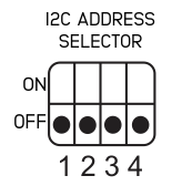
I2C Address Selection #
| DIP 2 | DIP 1 | DIP 3 | DIP 4 | Address |
|---|---|---|---|---|
| OFF | OFF | x | x | 0x73 |
| ON | OFF | x | x | 0x72 |
| OFF | ON | x | x | 0x71 |
| ON | ON | x | x | 0x70 |
Expansion Port #
Utilized GPIO Connections are highlighted in Green. They cannot be used for any other purpose with this module connected.
| PIN INDEX | Purpose | GPIO | SOURCE |
|---|---|---|---|
| 1 | MOSI | IO11 | ESP32-S3 |
| 2 | MISO | IO13 | |
| 3 | SCLK | IO12 | |
| 4 | GND | —- | |
| 5 | SCL | IO9 | |
| 6 | SDA | IO8 | |
| 7 | GND | —- | |
| 8 | RX1 | IO18 | |
| 9 | TX1 | IO17 | |
| 10 | GND | —- | |
| 11 | D+ | —- | |
| 12 | D- | —- | |
| 13 | GND | —- | |
| 14 | CS1 | P1_0 | PCA9539 I2C Address 0x75 |
| 15 | CS2 | P0_7 | |
| 16 | CS3 | P0_6 | |
| 17 | CS4 | P0_5 | |
| 18 | IO1 | IO1 | ESP32-S3 |
| 19 | IO2 | IO2 | |
| 20 | IO4 | IO4 | |
| 21 | IO5 | IO5 | |
| 22 | IO6 | IO6 | |
| 23 | IO7 | IO7 | |
| 24 | IO10 | IO10 | |
| 25 | IO11 | IO35 | |
| 26 | IO12 | IO36 | |
| 27 | IO13 | IO37 | |
| 28 | IO14 | IO14 | |
| 29 | RS485_TX | IO15 | |
| 30 | GND | —- | |
| 31 | GND | —- | |
| 32 | RS485_RX | IO16 | |
| 33 | P1_1 | P1_1 | PCA9539 I2C Address 0x75 |
| 34 | P1_2 | P1_2 | |
| 35 | IO21 | IO21 | ESP32-S3 |
| 36 | GND | —- | |
| 37 | GND | —- | |
| 38 | P1_3 | P1_3 | |
| 39 | P1_4 | P1_4 | |
| 40 | P1_5 | P1_5 | |
| 41 | IO39 | IO39 | ESP32-S3 |
| 42 | IO40 | IO40 | |
| 43 | NC | —- | |
| 44 | NC | —- | |
| 45 | NC | —- | |
| 46 | GND | —- | |
| 47 | 5V | 5V | |
| 48 | GND | GND | |
| 49 | 24V | 24V | |
| 50 | 24V | 24V |


