
Introduction #
The NORVI X-DI4 is an industrial-grade digital input expansion module designed to seamlessly integrate with the NORVI X Modular Controller. It provides four optically isolated and protected 24 V DC digital inputs, enabling reliable interfacing with sensors, switches, and other field devices used in industrial automation and monitoring systems.
The DI4 variant directly connects its inputs to the host CPU’s GPIO, offering high-speed signal capture suitable for PWM, pulse-train, and encoder inputs. Its design ensures noise immunity, galvanic isolation, and compatibility with both sourcing (PNP) and sinking (NPN) sensor types.
Product Features #
- 4 × Optically Isolated 24 V Digital Inputs
- Direct GPIO Link to Host CPU (for high-speed signal acquisition)
- Supports fast inputs such as PWM, pulse trains & encoders
- One common terminal for all four inputs
- DIN-rail mountable industrial enclosure
- Status indicators for each input
Applications #
- Industrial switch and sensor interfacing
- Counter and encoder signal reading
- Pulse input measurement and frequency monitoring
- Fast digital signal capture from machines or process lines
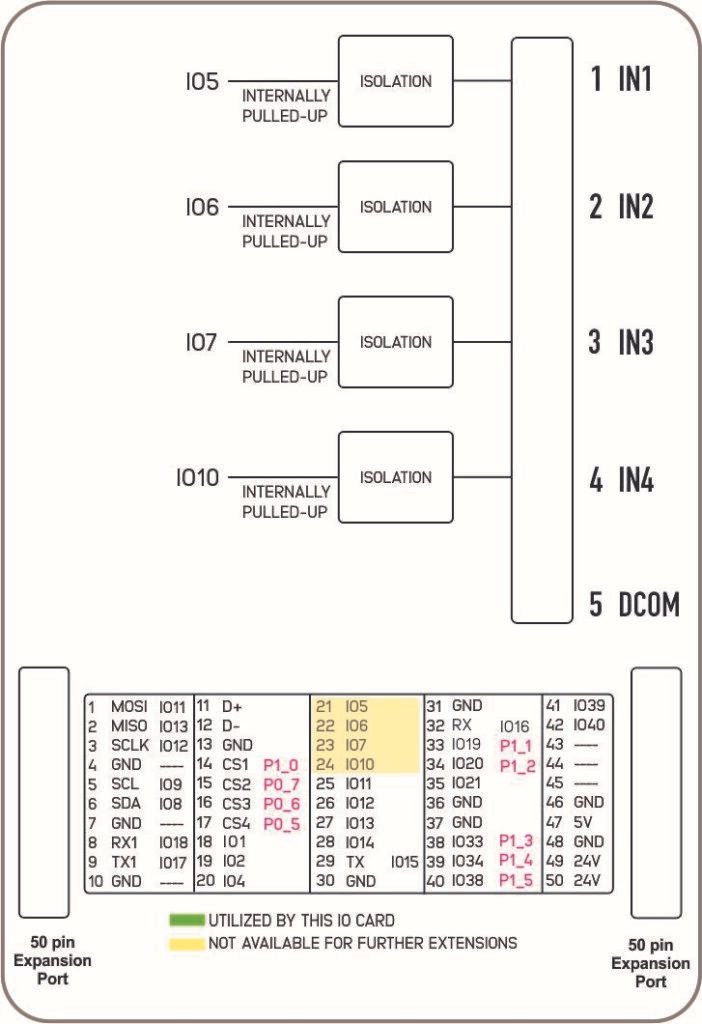
Product Block Diagram #
Technical Information #
Main #
| Range of Product | NORVI X |
| Product type | Expansion Module for NORVI X Series |
| Certifications | EN 61131-2:2007 EN 61010-1:2010+A1:2019 EN IEC 61010-2-201:2018 2014/30/EU- Electromagnetic Compatibility (EMC) Annex III, Part B, Module C |
| Rated supply voltage | 24V DC |
Complementary #
| Product Part Numbers | NORVI X-DI4 |
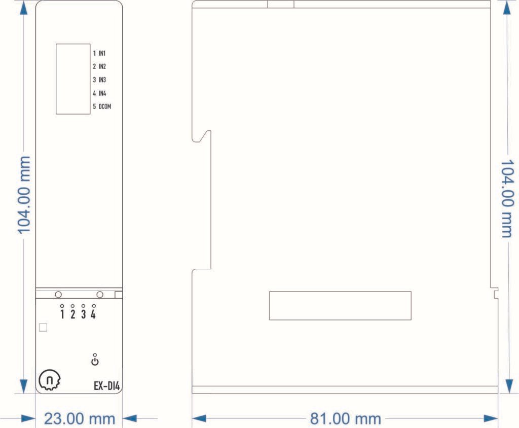
Mechanical Properties #
| Enclosure | NORVI X-N1 |
| Mounting / Installation Method | DIN RAIL |
| Terminal Type | Push-in terminal |
| Terminal Arrangement | Front |
| Length | 81.00 mm |
| Height | 104.00 mm |
| Width | 23.00 mm |
Environment #
| IP degree of protection | IP20 |
| Operating altitude | 0 – 2000 meters |
| Operating Temperature | –10 … +85° C (14…185 °F) |
| Storage altitude | 0 – 3000 meters |
| Shock resistance | 15 gn for 11ms |
| Resistance to electrostatic discharge | 4kV on contact 8kV on air |
| Resistance to electromagnetic fields | 10 V/m (80 MHz …… 1GHz) 3 V/m (1.4 MHz …… 2 GHz) 1 V/m (2 MHz …… 3 GHz) |
Electrical Characteristics #
Grid Powered Devices
| Rated Supply Voltage (V) | 24V DC |
| Current Consumption (mA) | 80mA @ 24VDC |
I/O Specifications #
| Parameter | Specification |
|---|---|
| Number of Inputs | 4 Digital Inputs |
| Input Type | Isolated 24 V DC (Supports Sinking sourcing) |
| Isolation Voltage | >1500 Vrms (optical isolation from CPU) |
| Input Voltage Range | 0 – 30 V DC |
| Logic Low (OFF) | < 5 V DC |
| Logic High (ON) | >15 V DC |
| Input Impedance | Approx. 3.3 kΩ |
| Input Current | ~ 7 mA @ 24 V DC |
| Switching Frequency | Up to 5 kHz (fast input mode) |
| Protection | Over-voltage, Reverse Polarity, ESD Protected |
| Isolation Type | Opto-coupler isolation per channel |
| Interface to CPU | NORVI X Expansion Port (Direct GPIO) |
| Status Indicators | 4 × LED Input Indicators |
| Power Supply | 24 V DC (shared with CPU via expansion port) |
| Communication Bus | Internal Expansion Bus |
| Connector Type | Push-in Terminal Block |
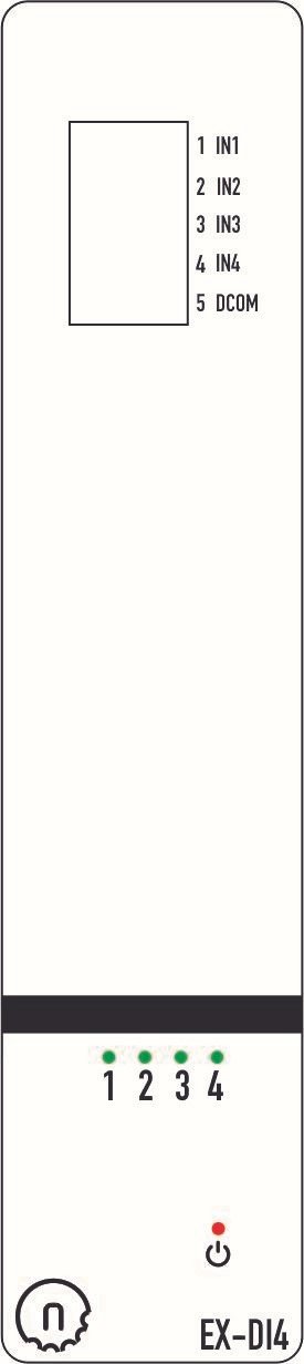
Terminal Configuration #
| Terminal | Description |
|---|---|
| IN1 | Digital Input 1 |
| IN2 | Digital Input 2 |
| IN3 | Digital Input 3 |
| IN4 | Digital Input 4 |
| DCOM | Isolated Digital Ground |
GPIO Utilization #
| Utilization | Connection to CPU |
|---|---|
| Digital Input 1 | IO5 |
| Digital Input 2 | IO6 |
| Digital Input 3 | IO7 |
| Digital Input 4 | IO10 |
Expansion Port #
Utilized GPIO Connections are highlighted in Yellow. They cannot be used for any other purpose with this module connected.
| PIN INDEX | Purpose | GPIO | SOURCE |
|---|---|---|---|
| 1 | MOSI | IO11 | ESP32-S3 |
| 2 | MISO | IO13 | |
| 3 | SCLK | IO12 | |
| 4 | GND | —- | |
| 5 | SCL | IO9 | |
| 6 | SDA | IO8 | |
| 7 | GND | —- | |
| 8 | RX1 | IO18 | |
| 9 | TX1 | IO17 | |
| 10 | GND | —- | |
| 11 | D+ | —- | |
| 12 | D- | —- | |
| 13 | GND | —- | |
| 14 | CS1 | P1_0 | PCA9539 I2C Address 0x75 |
| 15 | CS2 | P0_7 | |
| 16 | CS3 | P0_6 | |
| 17 | CS4 | P0_5 | |
| 18 | IO1 | IO1 | ESP32-S3 |
| 19 | IO2 | IO2 | |
| 20 | IO4 | IO4 | |
| 21 | IO5 | IO5 | |
| 22 | IO6 | IO6 | |
| 23 | IO7 | IO7 | |
| 24 | IO10 | IO10 | |
| 25 | IO11 | IO35 | |
| 26 | IO12 | IO36 | |
| 27 | IO13 | IO37 | |
| 28 | IO14 | IO14 | |
| 29 | RS485_TX | IO15 | |
| 30 | GND | —- | |
| 31 | GND | —- | |
| 32 | RS485_RX | IO16 | |
| 33 | P1_1 | P1_1 | PCA9539 I2C Address 0x75 |
| 34 | P1_2 | P1_2 | |
| 35 | IO21 | IO21 | ESP32-S3 |
| 36 | GND | —- | |
| 37 | GND | —- | |
| 38 | P1_3 | P1_3 | |
| 39 | P1_4 | P1_4 | |
| 40 | P1_5 | P1_5 | |
| 41 | IO39 | IO39 | ESP32-S3 |
| 42 | IO40 | IO40 | |
| 43 | NC | —- | |
| 44 | NC | —- | |
| 45 | NC | —- | |
| 46 | GND | —- | |
| 47 | 5V | 5V | |
| 48 | GND | GND | |
| 49 | 24V | 24V | |
| 50 | 24V | 24V |


