NORVI X is a next-generation modular industrial controller designed to power smart automation and IoT solutions. With a powerful CPU module and plug-and-play expansion modules, it scales up to 200 inputs and outputs – delivering unmatched flexibility, connectivity, and reliability.
Product Features #
- Based on ESP32-S3-WROOM
- TFT SPI Display with touch input
- Built-in RS-485 Communication
- Built-in Ethernet Communication
- DS3231 RTC
- DIN-Rail mount
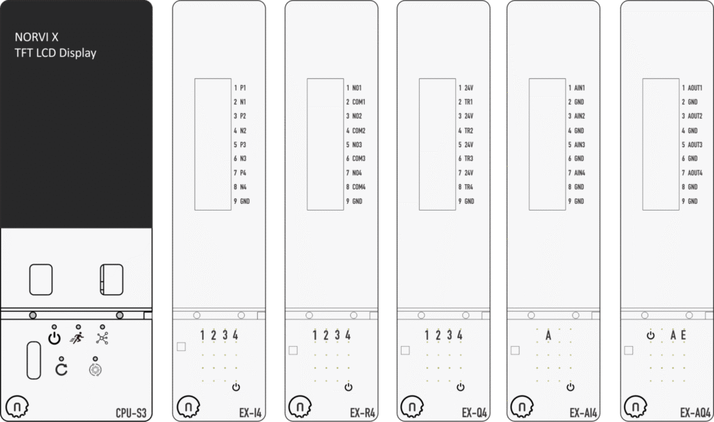
Expansions Supported #
| Digital Input Modules 4 x Digital Inputs 8 x Digital Inputs 16 x Digital Inputs | Relay Output Modules 4 x Relay Output 8 x Relay Output | Transistor Output Modules 4 x Transistor Output 8 x Transistor Output 16 x Transistor Output |
| Analog Input Modules 4 x Analog Inputs 0-10V 4 x Analog Inputs 4-20mA | Analog Output Modules 4 x Analog Outputs 0-10V / 4-20mA | Communication Modules Cellular Modem Quectel EC25 Cellular Modem SIMCOM A7672 |
| Power & Utility Modules 3 x Current Transformer (Energy) |
Product Block Diagram #
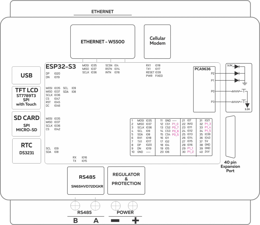
Main #
| Range of Product | NORVI X |
| Product type | Modular Programmable Controller |
| Certifications | EN 61131-2:2007 EN 61010-1:2010+A1:2019 EN IEC 61010-2-201:2018 2014/30/EU- Electromagnetic Compatibility (EMC) Annex III, Part B, Module C |
| Rated supply voltage | 24V DC |
| Communication | WiFI 2.5GHz / Bluetooth Ethernet RS-485 |
| Displays and Visual Indicators | 2.0 inch TFT LCD Display 240*320 |
Complementary #
| Product Unified Code | NORVI CPU-ESPS3-X1 |
| Product Part Numbers | NORVI CPU-ESPS3-X1 |
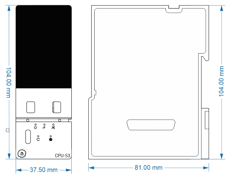
Mechanical Properties #
| Enclosure | NORVI X |
| Mounting / Installation Method | DIN RAIL |
| Terminal Type | Push-in terminal |
| Terminal Arrangement | Bottom |
| Length | 81.00 mm |
| Height | 104.00 mm |
| Width | 37.50 mm |
Environment #
| IP degree of protection | IP20 |
| Operating altitude | 0 – 2000 meters |
| Operating Temperature | –10 … +85° C (14…185 °F) |
| Storage altitude | 0 – 3000 meters |
| Shock resistance | 15 gn for 11ms |
| Resistance to electrostatic discharge | 4kV on contact 8kV on air |
| Resistance to electromagnetic fields | 10 V/m (80 MHz …… 1GHz) 3 V/m (1.4 MHz …… 2 GHz) 1 V/m (2 MHz …… 3 GHz) |
Electrical Characteristics #
| Rated Supply Voltage (V) | 24V DC |
| Current Consumption (mA) | 400mA |
| Recommended Power Source | 1A 24V DC |
Grid Powered Devices #
Processing #
| SOC / MCU | ESP32-S3-WROOM-1U-N16R2 |
| Flash Memory | 16MB |
| ROM | 384 KB |
| SRAM | 512 KB |
| PSRAM | 2 MB (Quad-SPI) |
Peripherals #
Built-in Buttons #
| Button 1 Pin | P0 | PCA9636 – IO Expander – I2C Address -0x41 |
| Button 2 Pin | P3 | PCA9636 – IO Expander – I2C Address -0x41 |
Built-in Indicators #
| RUN Indicator | P0 | PCA9636 – IO Expander – I2C Address -0x41 |
| ERROR Indicator | P3 | PCA9636 – IO Expander – I2C Address -0x41 |
LCD TFT #
| Display Driver | ST7789 |
| Display Size | 2.0 inch |
| MOSI | IO35 |
| MISO | IO37 |
| SCLK | IO36 |
| CS | IO47 |
| RST | IO45 |
| DC | IO46 |
| SCL Pin (Touch Screen) | IO9 |
| SDA Pin (Touch Screen) | IO8 |
| RESET Pin | NOT CONNECTED |
INPUTS and OUTPUTS #
An expansion module from NORVI Controllers should be used to add I/O to the CPU Module.
Refer products section Link for information on Expansion Modules.
Currently Available Expansion Modules are
- 4 x Digital Inputs
- 4 x Relay Outputs
- 4 x Transistor Outputs
- 4 x Analog Inputs 0-10V
- 4 x Analog Inputs 4-20mA
- 4 x Analog Outputs 0-10V / 4-20mA
- 8 x Digital Inputs
- 16 x Digital Inputs
- 8 x Relay Outputs
- 16 x Transistor Outputs
- Thermocouple x 4
- 8 x Transistor Outputs
Communication Channels #
RS-485 Communication #
| Communication Mode | HALF-DUPLEX |
| Transceiver | MAX485 |
| Unit Load | 1/4 |
| Flow Control / Direction Control Pin | Automatically Controlled |
| TX Pin | IO15 |
| RX Pin | IO16 |
| Terminal Arrangement | 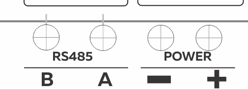 |
GPIO Map #
| GPIO | CPU (Utilization) | Expansion Port (Utilization) | Type / RTC | Typical Usage |
| 0 | BOOT Button | I/O/T (Yes) | Boot, GPIO | |
| 1 | SCSN – Ethernet | IO1 | I/O/T (Yes) | ADC input, touch pad |
| 2 | RSTN – Ethernet | IO2 | I/O/T (Yes) | ADC input, touch pad |
| 3 | I/O/T (Yes) | GPIO, JTAG control | ||
| 4 | INTN – Ethernet | IO4 | I/O/T (Yes) | ADC input, touch pad |
| 5 | IO5 | I/O/T (Yes) | ADC input, touch pad | |
| 6 | IO6 | I/O/T (Yes) | ADC input, touch pad | |
| 7 | IO7 | I/O/T (Yes) | ADC input, touch pad | |
| 8 | SDA | SDA | I/O/T (Yes) | ADC input, touch pad |
| 9 | SCL | SCL | I/O/T (Yes) | ADC input, touch pad |
| 10 | IO10 | I/O/T (Yes) | ADC input, touch pad | |
| 11 | IO11 | I/O/T (Yes) | ADC input, touch pad | |
| 12 | IO12 | I/O/T (Yes) | ADC input, touch pad | |
| 13 | IO13 | I/O/T (Yes) | ADC input, touch pad | |
| 14 | IO14 | I/O/T (Yes) | ADC input, touch pad | |
| 15 | RS485 – TX | IO15 | I/O/T (Yes) | UART flow control |
| 16 | RS485 – RX | IO16 | I/O/T (Yes) | UART flow control |
| 17 | MODEM – TX1 | I/O/T (Yes) | UART TX | |
| 18 | MODEM – RX1 | I/O/T (Yes) | UART RX | |
| 19 | USB – DP | I/O/T (Yes) | USB / UART1 RTS | |
| 20 | USB – DN | I/O/T (Yes) | USB / UART1 CTS | |
| 21 | IO21 | I/O/T | I²C SDA, GPIO | |
| 26 | I/O/T | PWM, GPIO | ||
| 27 | I/O/T | PWM, GPIO | ||
| 28 | I/O/T | Free only if no PSRAM | ||
| 29 | I/O/T | Free only if no PSRAM | ||
| 30 | I/O/T | Free only if no PSRAM | ||
| 31 | I/O/T | GPIO, SPI | ||
| 32 | I/O/T | JTAG TCK, GPIO | ||
| 33 | I/O/T | JTAG TDO, GPIO | ||
| 34 | I/O/T | JTAG TDI, GPIO | ||
| 35 | MOSI – TFT DISPLAY – SPI | I/O/T | JTAG TMS, GPIO | |
| 36 | SCLK – TFT DISPLAY – SPI | I/O/T | Serial RX | |
| 37 | MISO – TFT DISPLAY – SPI | I/O/T | Serial TX | |
| 38 | PCA9536 – RESET | I/O/T | Boot config | |
| 39 | IO39 | I/O/T | Boot config | |
| 40 | IO40 | I/O/T | Differential SPI | |
| 41 | RS485 – FC | I/O/T | Differential SPI | |
| 42 | SD CARD – CS | |||
| 43 | ||||
| 44 | ||||
| 45 | RESET – TFT DISPLAY | |||
| 46 | DC – TFT DISPLAY | |||
| 47 | CS – TFT DISPLAY | |||
| 48 | INTERRUPT – TOUCH PANEL |
Expansion Port #
| PIN INDEX | Purpose | GPIO | SOURCE |
|---|---|---|---|
| 1 | MOSI | IO35 | ESP32-S3 |
| 2 | MISO | IO37 | ESP32-S3 |
| 3 | SCLK | IO36 | ESP32-S3 |
| 4 | SCL | IO9 | ESP32-S3 |
| 5 | SDA | IO8 | ESP32-S3 |
| 6 | RX1 | IO18 | ESP32-S3 |
| 7 | TX1 | IO17 | ESP32-S3 |
| 8 | P1_2 | ESP32-S3 | |
| 9 | P1_1 | ESP32-S3 | |
| 10 | GND | —- | |
| 11 | GND | —- | |
| 12 | CS1 | P1_0 | PCA9539 I2C Address 0x75 |
| 13 | CS2 | P0_7 | PCA9539 I2C Address 0x75 |
| 14 | CS3 | P0_6 | PCA9539 I2C Address 0x75 |
| 15 | CS4 | P0_5 | PCA9539 I2C Address 0x75 |
| 16 | IO1 | IO1 | ESP32-S3 |
| 17 | IO2 | IO2 | ESP32-S3 |
| 18 | IO4 | IO4 | ESP32-S3 |
| 19 | IO5 | IO5 | ESP32-S3 |
| 20 | IO6 | IO6 | ESP32-S3 |
| 21 | IO7 | IO7 | ESP32-S3 |
| 22 | IN10 | IN10 | ESP32-S3 |
| 23 | IO11 | IO11 | ESP32-S3 |
| 24 | IO12 | IO12 | ESP32-S3 |
| 25 | IO13 | IO13 | ESP32-S3 |
| 26 | IO14 | IO14 | ESP32-S3 |
| 27 | IO15 | IO15 | ESP32-S3 |
| 28 | IO16 | IO16 | ESP32-S3 |
| 29 | P1_1 | P1_1 | PCA9539 I2C Address 0x75 |
| 30 | P1_2 | P1_2 | PCA9539 I2C Address 0x75 |
| 31 | IO21 | IO21 | ESP32-S3 |
| 32 | P1_3 | P1_3 | PCA9539 I2C Address 0x75 |
| 33 | P1_4 | P1_4 | PCA9539 I2C Address 0x75 |
| 34 | P1_5 | P1_5 | PCA9539 I2C Address 0x75 |
| 35 | IO39 | IO39 | ESP32-S3 |
| 36 | IO40 | IO40 | ESP32-S3 |
| 37 | 5V | 5V | |
| 38 | GND | GND | |
| 39 | GND | GND | |
| 40 | 24V | 24V |


