Overview #
This guide explains how to design, program, and deploy a professional graphical user interface (GUI) for the NORVI ESP32 HMI-7C using SquareLine Studio and Arduino LVGL.
Specifically, it demonstrates how to create an interactive interface to control transistor outputs, visualize 4–20 mA analog inputs, and monitor digital inputs.
Throughout this guide, you will learn how to set up the development environment, design the GUI using SquareLine Studio, export UI files, integrate them into Arduino projects, and finally compile and upload the firmware to the ESP-HMI-7C device.
Setting Up the Environment #
Before working with SquareLine Studio, first prepare the Arduino development environment.
For detailed, step-by-step instructions on:
- Installing the Arduino IDE
- Adding ESP32-S3 board
- Installing required libraries
- Testing the HMI configuration
Refer to the Getting Started with NORVI ESP32 HMI-7C document.
This guide ensures the environment is correctly configured before proceeding with GUI development.
Setting up the environment for SquareLine Studio #
Installing SquareLine Studio #
First, download the software from the official SquareLine Studio website, ensuring you select the version that is compatible with your operating system. After the download completes, start the installation by executing the downloaded file, following the on-screen instructions to set up (install) the software correctly.
Click here to download Squareline Studio
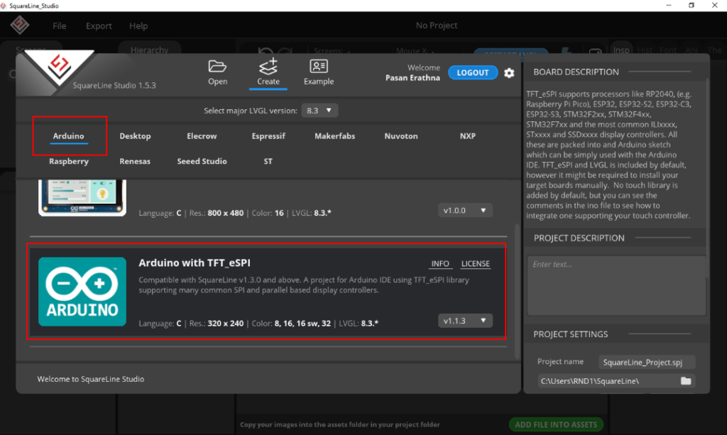
After successfully installing SquareLine Studio, launch the software. Next, a pop-up window will appear, where you should select “Create/Arduino” to initiate a new Arduino project.
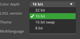
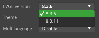
To customize the settings, navigate to the options shown below. First, set the 7-inch HMI resolution to 1024 × 600. Then, configure the color depth to 16-bit and ensure that the LVGL version matches the installed Arduino LVGL library version.
If the Arduino LVGL library version is below 8.3.11, please select LVGL version 8.3.6 here.
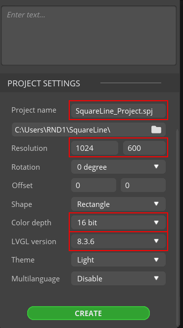
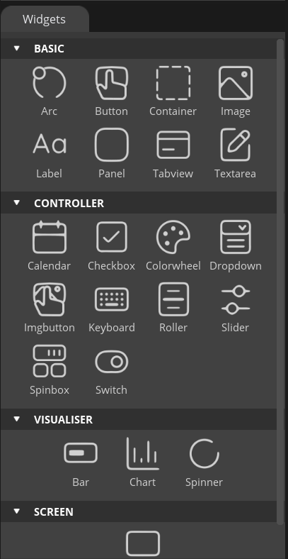
After confirming the LVGL version, proceed by selecting “Create” located in the lower right corner, which will unveil the following interface.
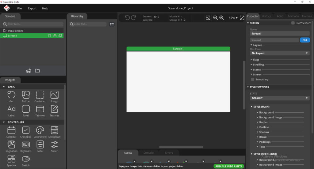
On the left-hand widget column, you will find a series of organized widgets. These include basic widgets such as ARC, buttons, images, and labels, control widgets like calendar, keyboard, and slider, and visualization widgets including bars, charts, and spinners. Additionally, the column features a dedicated category for screens.
Initiating a Project with SquareLine Studio #
Create a project #
- Create a project in SquareLine Studio to control LEDs via transistor outputs and to measure 4–20 mA analog current inputs and digital inputs.
- Use switch widgets to configure each transistor output with ON and OFF states for controlling the LEDs. Use arc widgets to measure the 4–20 mA analog current inputs, with the arcs scaled appropriately to the 4–20 mA range.
- Digital input states are measured and displayed using label widgets, showing values as “1” or “0”.
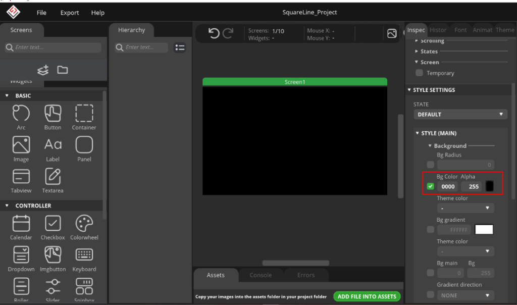
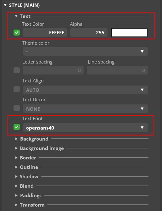
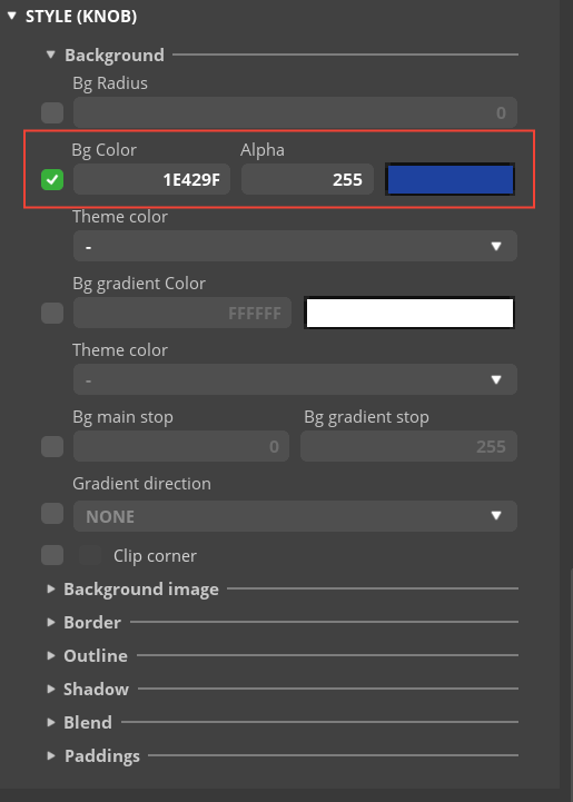
First, in this UI design, change the screen color to black, as shown in the figure below. This setting can be customized according to user preference.
It should incorporate custom fonts when adding labels within SquareLine Studio.
Font Selection & Integration #
Download a preferred font and seamlessly integrate it into the project by utilizing the “ADD FILE INTO ASSETS” option located at the bottom of the software interface.
Craft a font to your project’s needs by navigating to the ‘font menu’ located in the top right corner of SquareLine Studio.
Select the desired size, allowing for meticulous customization of the font to suit the project’s requirements.
- This project uses OpenSans in both Regular and Bold styles as the main fonts. You can download the required fonts directly from the OpenSans Font library to ensure proper display in your project.

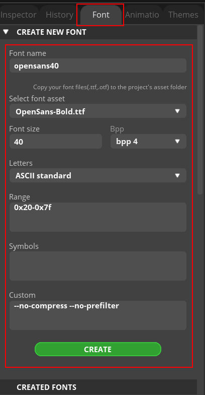
- Using these two OpenSans font files, the project creates three distinct fonts, which are illustrated below for reference.
| Font name | Asset | Font size | Bpp |
|---|---|---|---|
| Opensans26 | AsseOpenSans-Bold.ttf | 26 | 4 |
| Opensans34 | OpenSans-Regular.ttf | 34 | 4 |
| Opensans40 | OpenSans-Bold.ttf | 40 | 4 |
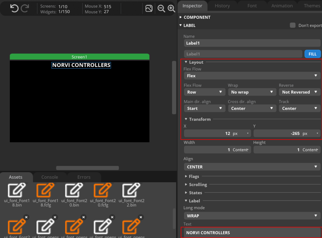
- Add the project title as “NORVI CONTROLLERS” on top of the screen.
Analog Inputs Configuration #
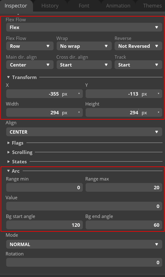
- Add Arc widgets to display the 4–20 mA analog input values. In this project, customized arcs are used to represent analog values. You need to create two types of arc images: one for an empty value (0 mA) and another for the maximum value (20 mA). Both arcs should be designed within a 256-pixel range to ensure consistency in the project.
- You must add these arc images to the project using the “Add file into Assets” button, following the same method you used to add fonts. Click here to download both customizable arcs.
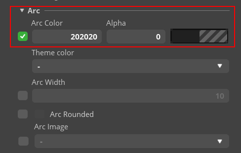
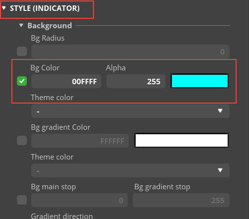
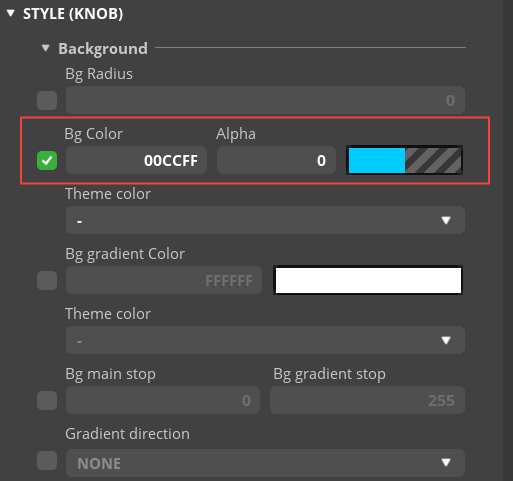
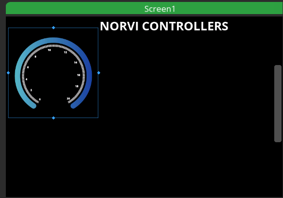
After adding the customized arcs to the Assets, add a new Arc widget to the screen. Configure its settings as shown in the figures below.
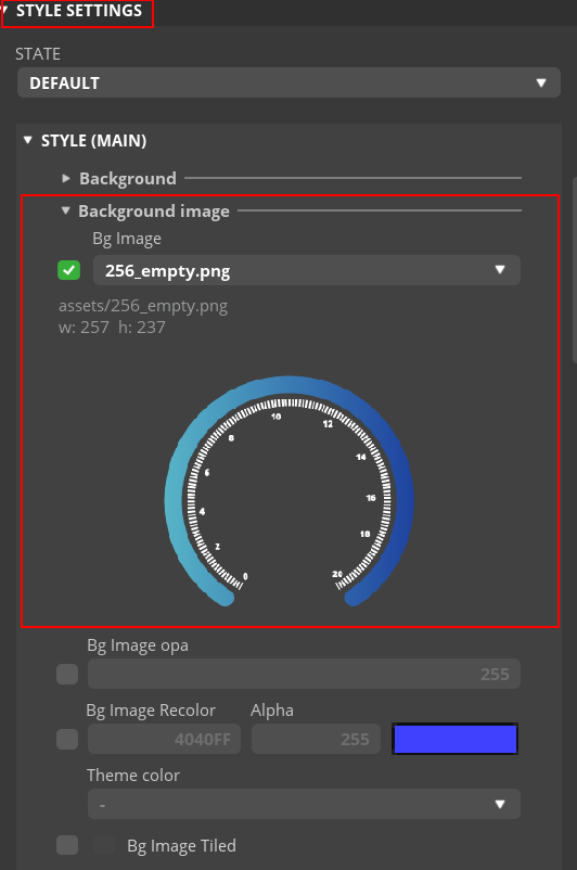
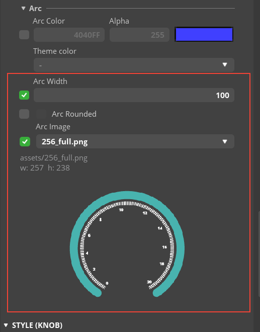
After applying the above settings, the Arc widget will display an output as shown below.
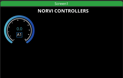
- Next, add an Arc Label and a Value Label to name the arc and display the 4–20 mA analog input value.
- The Value Labels are named AI1, AI2, AI3, and AI4, with the text color set to #57b4c7.
- Both labels use OpenSans34 as the font size.
- After applying these styles, the final appearance of the 4–20 mA analog indicator will be as shown below.
For the four analog inputs, create four copies of the design described above, ensuring each has the correct naming.
Transistor Outputs Configuration #
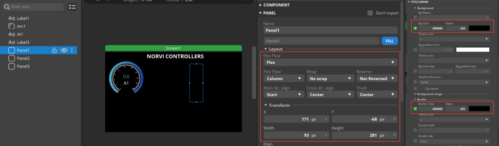
- To control the transistor outputs, add three Panel widgets as shown below for the transistor output labels, values, and switches.
- The transistor output labels and value labels use the same design style as the analog input labels, with OpenSans26 as the font. The value labels should be named TR1, TR2, TR3, and TR4.
- The figures below illustrate how to add switches to the screen for controlling the transistor outputs.

- Rename the switches as SWTR1, SWTR2, SWTR3, and SWTR4.
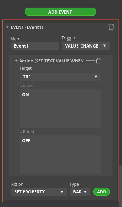
- Next, add events to each Switch widget as shown below, ensuring the correct targets are assigned: TR1, TR2, TR3, and TR4.
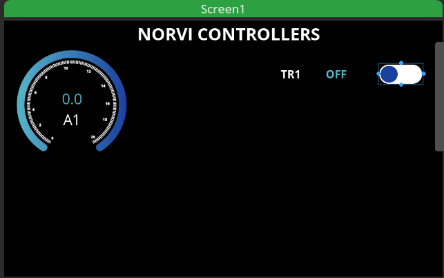
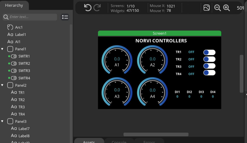
- After adding a transistor output controller, the screen will appear as shown in the figure below.
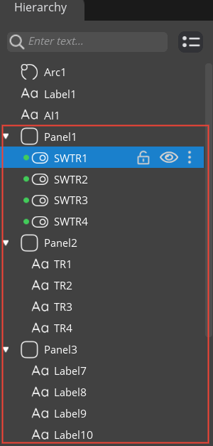
- Following the steps above, add four transistor output controls with the correct names as previously mentioned. The final hierarchy of the transistor outputs should appear as shown in the figure below.
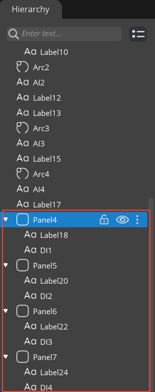
Digital Inputs Configuration #
- For the digital input readings, create four separate panels, each containing a name label and a value label.
- The value labels should be named DI1, DI2, DI3, and DI4.
- The style settings for all labels should match those used for the transistor output labels.
- The figure below illustrates how the hierarchy is defined.
The final design will appear as shown in the image below.
- Create a new folder in any location on your PC and give it an appropriate name.
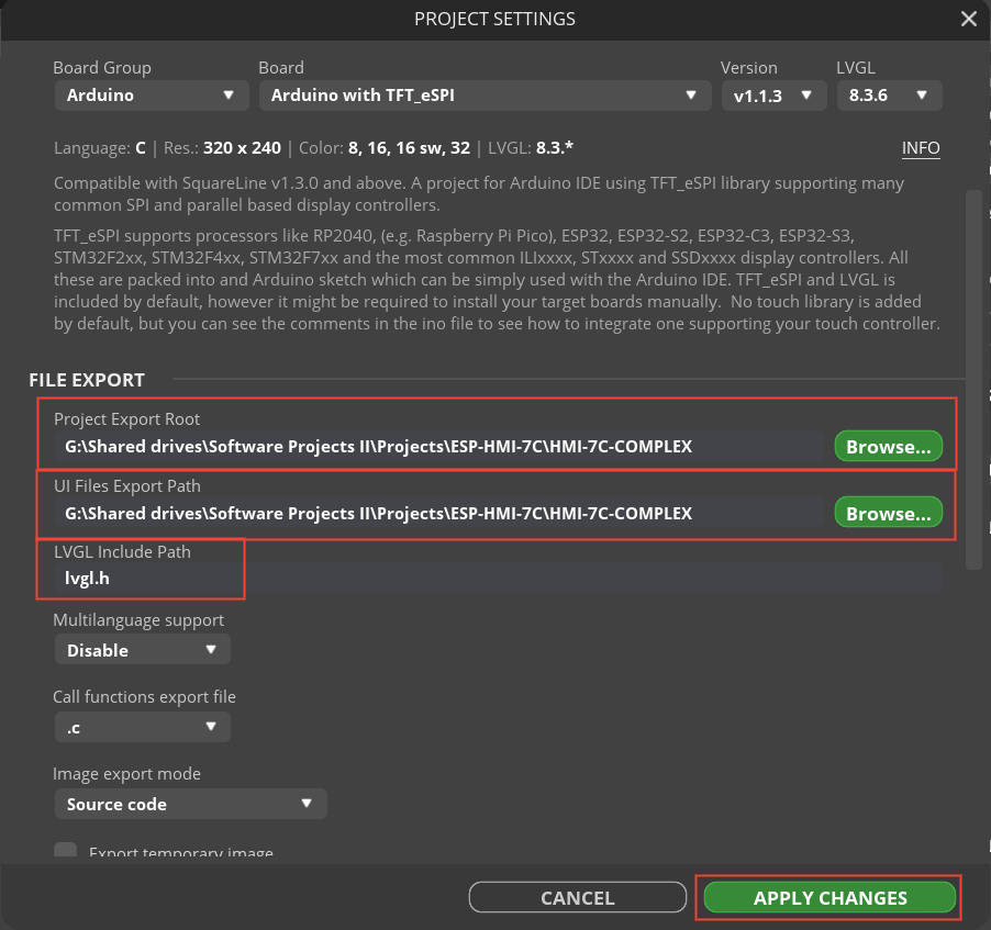
- Go to File → Project Settings and make the necessary changes in the pop-up window.
- Browse and set the Project Export Root and UI Files Export Path to the folder you just created.
- After making the changes, click “APPLY CHANGES” in the lower-right corner to save the settings.
Then select File/Save to save the project file and Export/Export UI Files to export the project.
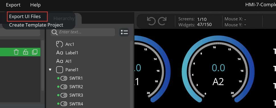
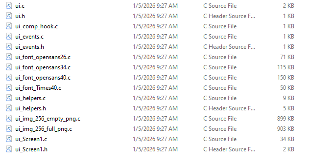
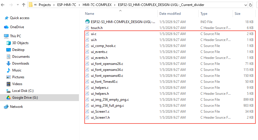
- After that inside above set path, UI files can be found.
Programing Scenario #
Download the example program corresponding to your ESP-HMI-7C category from the links provided below.
- 4-20 Analog current inputs – ESP-HMI-7C Current divider
- 4-20 Analog voltage inputs – ESP-HMI-7C Voltage divider
Next, copy the exported UI files and paste them into the downloaded example project folder. This will replace the existing UI files in the example project.
Next, open the ui_screen1.c file and update the switch events as shown below.
void ui_event_SWTR1(lv_event_t * e)
{
  if (lv_event_get_code(e) == LV_EVENT_VALUE_CHANGED) {
    lv_obj_t * target = lv_event_get_target(e);
    bool state = lv_obj_has_state(target, LV_STATE_CHECKED);
    setTransistorState(1, state);
    lv_label_set_text(ui_TR1, state ? "ON" : "OFF");
  }
}


void ui_event_SWTR2(lv_event_t * e)
{
  if (lv_event_get_code(e) == LV_EVENT_VALUE_CHANGED) {
    lv_obj_t * target = lv_event_get_target(e);
    bool state = lv_obj_has_state(target, LV_STATE_CHECKED);
    setTransistorState(2, state);
    lv_label_set_text(ui_TR2, state ? "ON" : "OFF");
  }
}

void ui_event_SWTR3(lv_event_t * e)
{
  if (lv_event_get_code(e) == LV_EVENT_VALUE_CHANGED) {
    lv_obj_t * target = lv_event_get_target(e);
    bool state = lv_obj_has_state(target, LV_STATE_CHECKED);
    setTransistorState(3, state);
    lv_label_set_text(ui_TR3, state ? "ON" : "OFF");
  }
}

void ui_event_SWTR4(lv_event_t * e)
{
  if (lv_event_get_code(e) == LV_EVENT_VALUE_CHANGED) {
    lv_obj_t * target = lv_event_get_target(e);
    bool state = lv_obj_has_state(target, LV_STATE_CHECKED);
    setTransistorState(4, state);
    lv_label_set_text(ui_TR4, state ? "ON" : "OFF");
  }
}
Open the ui_screen1.h file and add the setTransistorState function.
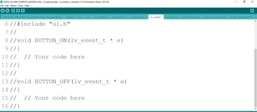
void setTransistorState(uint8_t output, bool state);Comment out the entire code in the ui_events.c file.
Compile and Upload #
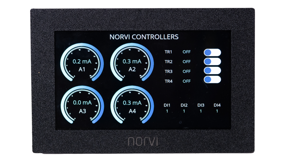
After compiling and uploading the program, the ESP-HMI-7C user interface should appear as shown below.
Alternatively, you can directly download the example programs from the links provided below, then compile and upload them to the ESP-HMI-7C to achieve the same interface.
- 4-20 Analog current inputs – ESP-HMI-7C Current divider
- 4-20 Analog voltage inputs – ESP-HMI-7C Voltage divider