
Overview #
The NORVI ESP-HMI-7C is an ESP32-based HMI controller with a 7-inch RGB touchscreen, designed for industrial monitoring and control applications. It supports RS485 communication, making it suitable to implement NORVI 7″ HMI as a MODBUS master with field sensors and devices.
In this application, the ESP-HMI-7C operates as a MODBUS Master and communicates with an XY-MD02 temperature and humidity sensor over RS485. The device periodically reads Modbus input registers from the sensor, converts the raw values into real-world units, and displays the data on an LVGL-based graphical user interface.
The measured temperature and humidity values are visualized using:
- Numeric readouts
- A vertical thermometer bar for temperature
- A circular arc indicator for humidity
- Status zones such as COLD / WARM / HOT and DRY / COMFORT / HUMID
This guide explains how to configure the ESP-HMI-7C as a Modbus master, read data from the XY-MD02 sensor, and present real-time sensor values on the HMI display.
MODBUS Protocol #
MODBUS is a serial communication protocol developed and published by Modicon in 1979 for use with its programmable logic controllers (PLCs). Simply put, it is a method for transmitting information over serial lines between electronic devices. In this setup, the device requesting information is called the MODBUS Master (Client), while the devices providing information are MODBUS Slaves (Servers). A standard MODBUS network consists of one Master and up to 247 Slaves, each assigned a unique Slave ID from 1 to 247. Additionally, the Master can write information to the Slaves, enabling full two-way communication.
Several versions of the MODBUS protocol exist for the serial port and Ethernet and the most common are:
- MODBUS RTU
- MODBUS ASCII
- MODBUS TCP
- MODBUS Plus
How does it work? #
MODBUS communication occurs over serial lines between devices. The simplest setup involves a single serial cable connecting the serial ports of two devices: a Client and a Server. MODBUS data is transmitted as a series of ones and zeroes, called bits, with each bit represented by a voltage – zeroes as positive voltage and ones as negative voltage. The system transmits these bits rapidly, typically at 9600 baud (bits per second), ensuring efficient and reliable serial communication between devices.
Check this link to understand more about the MODBUS protocol.
RTU (RS485) Mode #
MODBUS RTU, designed specifically for serial communication, uses interfaces such as RS-232 and RS-485. When controllers operate on a MODBUS network in RTU (Remote Terminal Unit) mode, each 8-bit byte in a message contains two 4-bit hexadecimal characters. The key advantage of MODBUS RTU is its higher character density, which delivers better data throughput than MODBUS ASCII at the same baud rate. Additionally, the system transmits each message as a continuous data stream, ensuring efficient and reliable communication.
The format for each byte in RTU mode is:
Coding System
- 8-bit binary, hexadecimal 0-9, A-F
- Two hexadecimal characters are contained in each
- 8-bit field of the message
Bits per Byte
- 1 start bit
- 8 data bits, the least significant bit sent first
- 1 bit for even/odd parity; no bit for no parity
- 1 stop bit if parity is used; 2 bits if no parity
Error Check Field
- Cyclical Redundancy Check (CRC)
NORVI ESP-HMI-7C as a MODBUS Master #
MODBUS has many protocol versions, but in this instructable, we will use MODBUS RTU, which is ideal for serial communication with RS-232 or RS-485 interfaces. Here we’ll be considering the NORVI ESP-HMI-7C device as a master and “XY-MD02” sensor will be the slave.
Hardware Setup #
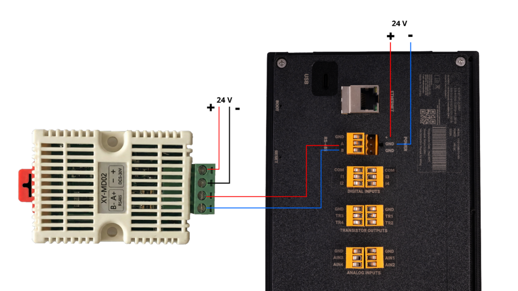
- Connect XY-MD02 sensor to ESP-HMI-7C’s RS-485 line and powered the sensor and HMI using 24V as figure 1.
GUI Design Setup #
- For a detailed guide on designing the GUI design using Squareline Studios, please refer to: Guide on GUI Designing using Squareline Studios
- In above guide include how to add arc widgets,labels and how to customize them.
- You can download the customized arcs used for this project from GitHub Repo.
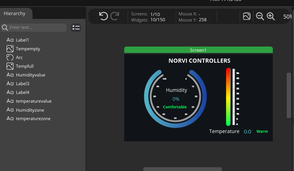
- Your final design will appear like image below
- Download the complete SquareLine Studio project file (.spj). If needed, you may review it and customize it according to your preferences.
Software Setup #
For step-by-step instructions on setting up the Arduino IDE and LVGL, refer to the Getting Started with NORVI ESP32 HMI-7C document.
Add required libraries
- PCA9538.h library – PCA9538
- PCA9536D.h library – PCA9536
- ModbusMaster.h library – ModbusMaster
Pin Configurations #
- The system uses the RX and TX pins for RS485 communication. Because the RS485 channel supports automatic switching between master and slave modes, it does not require an FC (Flow Control) pin. As a result, the system eliminates the need for pre-transmission or post-transmission control, simplifying the communication process.
#define RS485_RXD 2
#define RS485_TXD 9 - The system uses a PCA9536 GPIO expander to configure the UART selection pin. Because both GSM and RS485 interfaces share the same UART line, this pin controls the communication mode. When the UART selection pin is set to HIGH, the system switches to GSM communication. Conversely, setting the pin to LOW configures the system to operate in RS485 communication mode.
#define UART_SEL 3- Create the PCA9536 object as below.
PCA9536 PortIO;- Create Modbusmaster node object as below.
ModbusMaster node;Setup function
- Configure the serial1 line for RS485 communication.
Serial1.begin(9600, SERIAL_8N1, RS485_RXD, RS485_TXD);- Begin the PCA9536 expander object.
if (PortIO.begin() == false)
{
Serial.println("PCA9536 not detected. Please check wiring. Freezing...");
while (1);
}- Make the UART selection pin to LOW for RS485 communication.
PortIO.pinMode(UART_SEL, OUTPUT);
PortIO.digitalWrite(UART_SEL, LOW);
delay(100);- Begin the modbus master device communication.
node.begin(1, Serial1); // XY-MD02 default ID = 1- Create lvgl callback function to update HMI in every one second.
lv_timer_create(GPIOCallback, 1000, NULL);Read temperature and humidity data from the XY-MD02 Modbus sensor. The reading starts from input register 0x0001 and spans two registers.
uint8_t result = node.readInputRegisters(0x0001, 2);  // read Temp + Hum
float temperature = NAN, humidity = NAN;
if (result == node.ku8MBSuccess) {
  int16_t tempRaw = (int16_t)node.getResponseBuffer(0);  // signed
  uint16_t humRaw = node.getResponseBuffer(1);           // unsigned
  temperature = tempRaw / 10.0;
  humidity = humRaw / 10.0;
LVGL functions to display values #
- Display numeric values in labels
char buf[16];
snprintf(buf, sizeof(buf), "%.1f °C", temperature);
lv_label_set_text(ui_temperaturevalue, buf);

snprintf(buf, sizeof(buf), "%.1f %%", humidity);
lv_label_set_text(ui_Humidityvalue, buf);- The temperature filling bar maps values from 0°C to 50°C, with 0°C at the bottom and 50°C representing the full height of the bar.
// --- Temperature Bar Fill (0–50 °C mapped to 0–full height) ---
int fullHeight = lv_obj_get_height(ui_Tempempty);  // height of background
int fillHeight = (int)((temperature / 50.0) * fullHeight);
if (fillHeight < 0) fillHeight = 0;
if (fillHeight > fullHeight) fillHeight = fullHeight;

// Resize ui_Tempfull to match value
lv_obj_set_height(ui_Tempfull, fillHeight);

// Align fill to bottom of the thermometer
lv_obj_align_to(ui_Tempfull, ui_Tempempty, LV_ALIGN_BOTTOM_MID, 0, 0);- The humidity arc maps values from 0 to 100, representing the humidity percentage, with 0 at the start of the arc and 100 at the end.
// --- Humidity Arc (0–100%) ---
int arc_val = (int)humidity;
if (arc_val < 0) arc_val = 0;
if (arc_val > 100) arc_val = 100;
lv_arc_set_value(ui_Arc, arc_val);- Define temperature zones according to different temperature value ranges.
// --- Temperature Zone (0–50 °C) ---
if (temperature < 20) {
  lv_label_set_text(ui_temperaturezone, "COLD");
  lv_obj_set_style_text_color(ui_temperaturezone, lv_color_hex(0x00FF51), 0);  // green
} else if (temperature < 35) {
  lv_label_set_text(ui_temperaturezone, "WARM");
  lv_obj_set_style_text_color(ui_temperaturezone, lv_color_hex(0xFFF200), 0);  //yellow
} else {
  lv_label_set_text(ui_temperaturezone, "HOT");
  lv_obj_set_style_text_color(ui_temperaturezone, lv_color_hex(0xFF0000), 0);  // red
}- Define Humidity zones according to different humidity percentages.
// --- Humidity Zone (0–100%) ---
if (humidity < 40) {
  lv_label_set_text(ui_Humidityzone, "DRY");
  lv_obj_set_style_text_color(ui_Humidityzone, lv_color_hex(0x00FF51), 0);  // green
} else if (humidity < 70) {
  lv_label_set_text(ui_Humidityzone, "COMFORT");
  lv_obj_set_style_text_color(ui_Humidityzone, lv_color_hex(0xFFF200), 0);  // yellow
} else {
  lv_label_set_text(ui_Humidityzone, "HUMID");
  lv_obj_set_style_text_color(ui_Humidityzone, lv_color_hex(0xFF0000), 0);  // red
}- Please refer below configured GitHub link for full program: ESP32-HMI-7C Modbus Master Program
Displaying values in HMI #
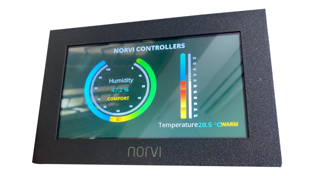
As shown in the image below, the HMI display presents the current temperature and humidity readings, allowing you to monitor your environment.
Troubleshooting #
| Issue | Possible Cause | Solution |
|---|---|---|
| Modbus read fails or returns errors | RS485 wiring issues, incorrect UART selection, or wrong sensor ID | Verify RS485 connections, ensure UART_SEL is set LOW, and confirm the XY-MD02 slave ID matches the code |
| Unexpected resets or freezes | Electrical noise or timing issues on RS485 | Add delay after Modbus read, ensure proper RS485 termination, and check power supply stability |
| GUI not updating | LVGL timer handler not running or display not initialized | Ensure lv_timer_handler() is called in the main loop and the display is correctly initialized |
| Temperature value shows as a box or incorrect symbol | The font used does not support the degree (°) symbol | Use OpenSans with ASCII Extended when exporting the font from SquareLine Studio |
| Vertical thermometer bar cuts off at the bottom | Resizing images directly instead of using a Bar widget | Use the LVGL Bar widget with an indicator image aligned to the bottom |
| Humidity arc does not display correctly | Arc value exceeds 0–100% range | Ensure the value passed to lv_arc_set_value() is clamped between 0 and 100 |
- Always power off the system before changing RS485 wiring.
- Verify I2C GPIO expanders and touch controller addresses using a simple I2C scanner.
- Check serial monitor for Modbus error codes to identify communication issues.


