Product Features #
- ESP32-WROOM32 Module
- Solar Battery Power
- LTE Connections
- Load Cell Input
Cellular Communication LTE1
- Module – SIM7000
- Brand Name – SIMCom
- FCC ID – 2AJYU-SIM7000
- TAC – 86615402
Cellular Communication LTE2
- Module – SIM7500
- Brand Name – SIMCom
- FCC ID – 2AQ9M-SIM7500
- TAC – 86147503
Main #
| Range of Product | NORVI EC M11 |
| Product Type | Programmable Node |
| Certifications | EN 61131-2:2007 EN 61010-1:2010+A1:2019 EN IEC 61010-2-201:2018 2014/30/EU- Electromagnetic Compatibility (EMC) Annex III, Part B, Module C |
| Rated supply voltage | 24V DC |
| Communication | WiFI / Bluetooth LTE1 / EDGE – SIMCOM SIM7000 LTE2 / EDGE – SIMCOM SIM7500 |
| Inputs and Outputs | 1 x Load Cell Input |
| Displays and Visual Indicators | LED |
Complementary #
| Product Unified Code | NORVI EC-M11-BC-C3-LTE |
| Product Part Numbers | NORVI EC-M11-BC-C3-LTE |
Mechanical Properties #
| Enclosure | WP8-10-4G |
| Mounting / Installation Method | Wall mount Electrical Pole mount – accessory required |
| Terminal Type | 8 Position Molding Cable / AWG24 / Length 2 meters |
| Terminal Arrangement | Color-Coded Tinned Wires |
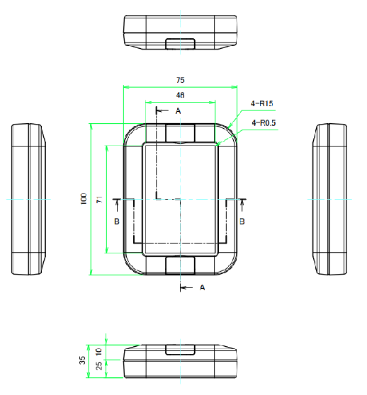
| Depth | 35 mm |
| Height | 100 mm |
| Width | 75 mm |
Environment #
| IP degree of protection | IP20 |
| Operating altitude | 0 – 2000 meters |
| Operating Temperature | – –10 … +85° C |
| Storage altitude | 0 – 3000 meters |
| Shock resistance | 15 gn for 11ms |
| Resistance to electrostatic discharge | 4kV on contact 8kV on air |
| Resistance to electromagnetic fields | 10 V/m (80 MHz …… 1GHz) 3 V/m (1.4 MHz …… 2 GHz) 1 V/m (2 MHz …… 3 GHz) |
Processing #
| SOC / MCU | ESP32-WROOM32 |
| Flash Memory | 4MB |
| ROM | 448 KB |
| SRAM | 520 KB |
| PSRAM | NOT AVAILABLE |
Indicators #
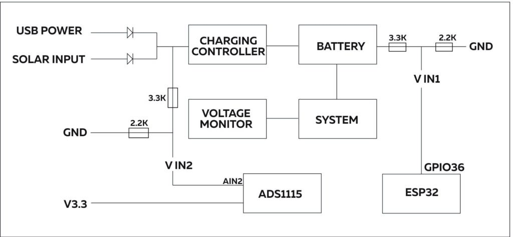
To activate the LEDs for the solar connection, the voltage should be at least 5V.
| RED LED ON | The device is powered on |
| GREEN LED ON | The battery is connected. |
| GREEN LED BLINK | The battery is not connected. |
INPUTS and OUTPUTS #
Load Cell Input #
| Number of Load Cell Inputs | 1 |
| Module Type | HX711 |
| PD SCK | GPIO12 |
| DOUT | GPIO13 |
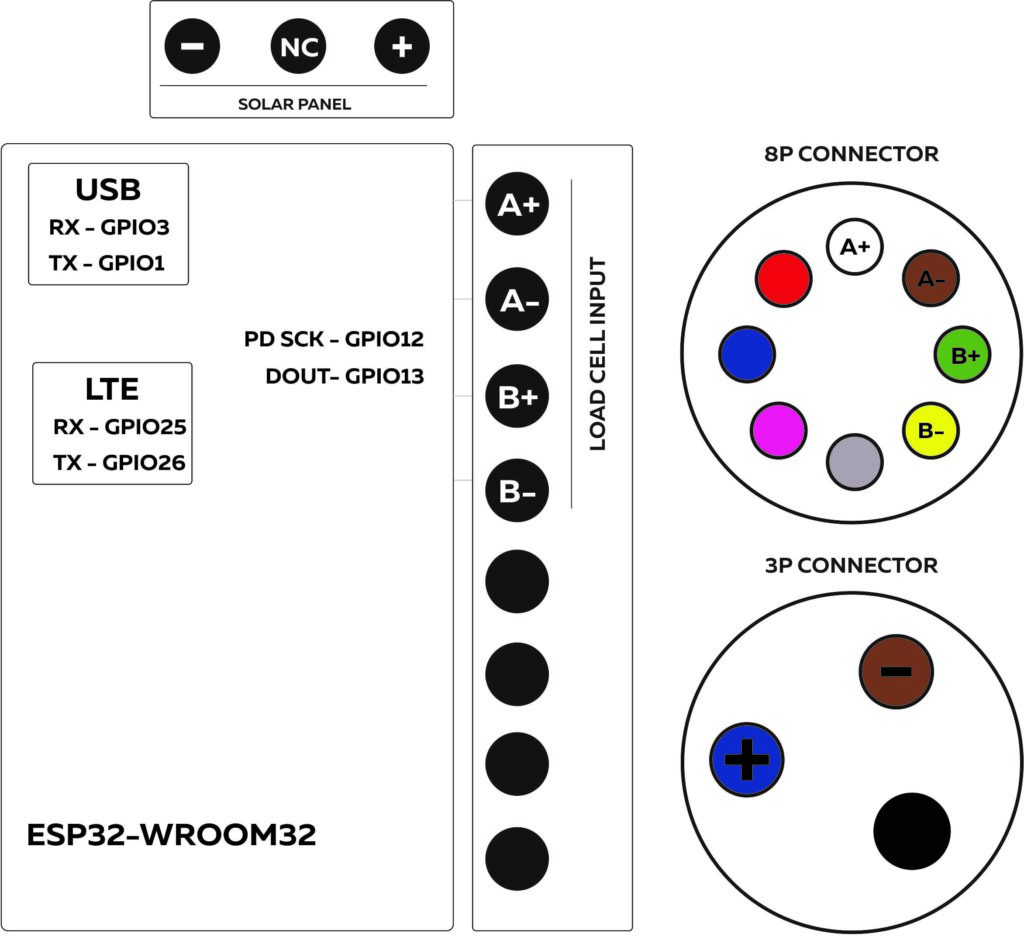
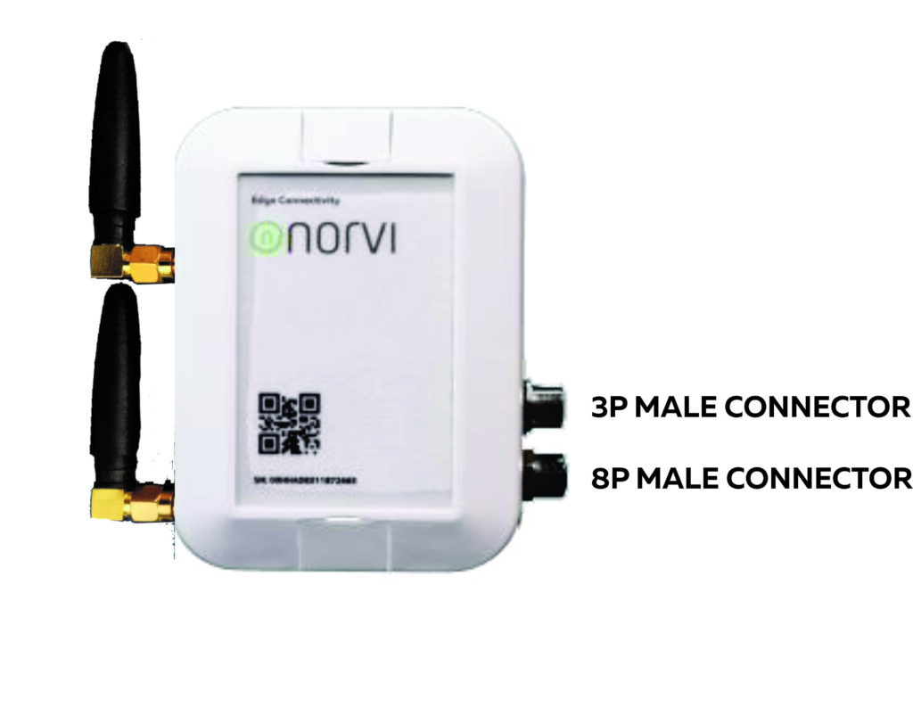
This product includes two connectors: an 8-pin male connector and a 3-pin male connector, which are connected as shown in the figure below.
8-pin and 3-pin connectors and wire harness #
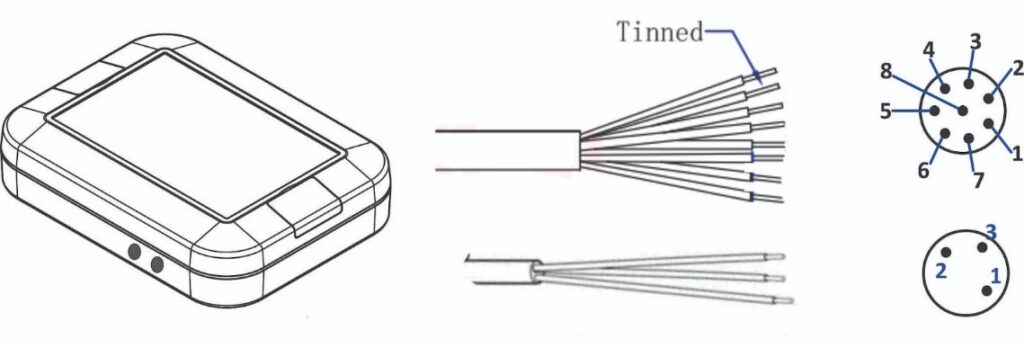
Pin Description #
| 8P Male | Wire color | I/O Configuration |
| 1 | White | A+ |
| 2 | Brown | A- |
| 3 | Green | B+ |
| 4 | Yellow | B- |
| 5 | Gray | – |
| 6 | Pink | – |
| 7 | Blue | – |
| 8 | Red | – |
| 3P Male | Wire color | I/O Configuration |
| 1 | Blue | Solar Panel + |
| 2 | Black | Not In Use |
| 3 | Brown | Solar Panel – |
Solar Input #
| Solar-Powered Model | CN3083 |
| Maximum Charge Current | 600mA |
| Maximum Voltage | 6V |
Battery #
| Battery Type | 103040 Lithium polymer battery |
| Nominal Capacity | 1200mAh |
| Nominal Voltage | 3.75V |
| Overcharge | 4.2V |
| Over-discharge Cutoff Voltage | 3V |
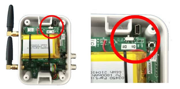
The battery power switch and USB (mini) port can be accessed from this location.
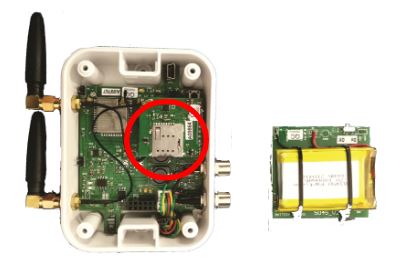
The SIM card should be inserted into the designated slot following the removal of the battery, as depicted in the provided image. Once the SIM card is properly inserted, reconnect the battery to the headers.
LTE1 Communication #
| Model of LTE Modem | SIM7000-E |
| FCC ID | 2AJYU-SIM7000 |
| TAC | 86615402 |
| RXD | GPIO25 |
| TXD | GPIO26 |
| RESET | GPIO32 |
| POWER | GPIO22 |
LTE2 Communication #
| Model of LTE Modem | SIM7500 |
| FCC ID | 2AQ9M-SIM7500 |
| TAC | 86147503 |
| RXD | GPIO25 |
| TXD | GPIO26 |
| RESET | GPIO27 |
| POWER | GPIO32 |
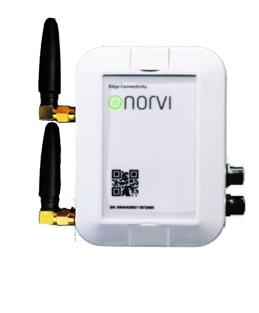
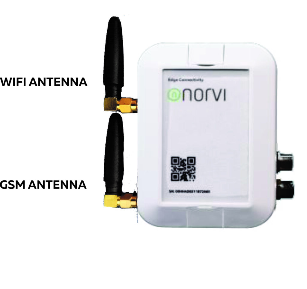
This product features two antennas, a WIFI antenna and a GSM antenna, which are integrated according to the configuration depicted in the figure below.
GPIO Map #
| 0 | outputs PWM signal at boot | NRST |
| 1 | USB to UART | TX0 |
| 2 | ||
| 3 | USB to UART | RX0 |
| 4 | ||
| 5 | outputs PWM signal at boot | |
| 12 | Load Cell Input | PD SCK |
| 13 | Load Cell Input | DOUT |
| 18 | ||
| 23 | ||
| 25 | LTE Modem | RX |
| 26 | LTE Modem | TX |
| 27 | LTE Modem | RESET |
| 32 | LTE Modem | Power |
| 38 | ||
| 39 |


