
Overview #
This document presents a comprehensive low-power application study for the EC-M12-BC-C6-C-A, a battery-powered industrial data logger designed for remote monitoring using 4–20 mA sensors and NB-IoT / LTE-M cellular connectivity.
The study demonstrates a real-world use case where the device interfaces with a 4–20 mA diesel fuel tank level sensor, processes the analog signal using a high-resolution ADC, and transmits fuel level, battery status, and fault information to a ThingsBoard IoT dashboard via MQTT over a 4G cellular network.
For a detailed guide on setting up ThingsBoard, please refer to: Connecting ESP32 to ThingsBoard over Wi-Fi
Key aspects covered include:
- End-to-end system architecture (sensor → MCU → cellular modem → cloud dashboard)
- Hardware and software configuration for ultra-low-power operation
- Duty-cycled operating workflow optimized for battery longevity
- Measured power consumption profiling across all operating stages
- Battery life estimation for different data transmission intervals
- Reliability considerations, including sensor fault detection and cellular network behavior
The results show that by combining STM32 low-power modes, controlled sensor powering, efficient cellular communication, and extended sleep intervals, the system can achieve multi-year battery life, making it well suited for remote industrial monitoring applications such as fuel tanks, reservoirs, and utility infrastructure.
Initial setup #
- Firstly, power source is configured as USB by setting on-board jumper to position 2.
- To setup the Arduino IDE to program the STM32L0 microcontroller please refer to :EC-M12-BC-C6-C-A-Initial_setup
- The exported binary file can be uploaded to STM32 microcontroller through a ST-Link Programmer.
- The connections GROUND, CLK, DIO, RESET should be connected with the ST-Link Programmer.
Hardware setup #
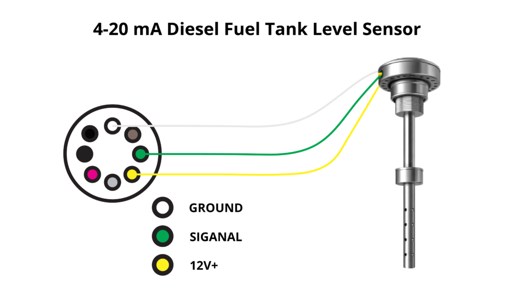
Connect 4-20mA Diesel Fuel Tank Level Sensor to 8 pin connector’s 4-20mA analog input and powered the sensor using 12V output as figure 1.
After that change the power source to battery power by setting the on-board jumper to position 1.
Software setup #
- Define all MCU pin configurations according to the EC-M12-BC-C6-C-A datasheet.
- Initialize the STM32 low-power framework.
- Initialize and configure the SIM7070 cellular modem.
- Establish cellular network and GPRS connectivity.
- Configure the MQTT broker (ThingsBoard) and device access token.
- Initialize the ADS1115 ADC for 4–20 mA analog current measurement.
- Enable the booster and analog front-end circuitry.
- Read 4–20 mA diesel fuel level sensor current values.
- Convert current values to fuel level percentage and fuel height.
- Read battery voltage through the ADC channel.
- Detect sensor fault conditions (open/short circuit).
- Publish telemetry data to the ThingsBoard dashboard via MQTT.
- Disable ADC, communication interfaces, and booster circuitry.
- Enter low-power shutdown mode for 15 minutes.
Please refer below configured GitHub link for full program: EC-M12-BC-C6-C-A 4-20mA sensor
Operating Workflow #
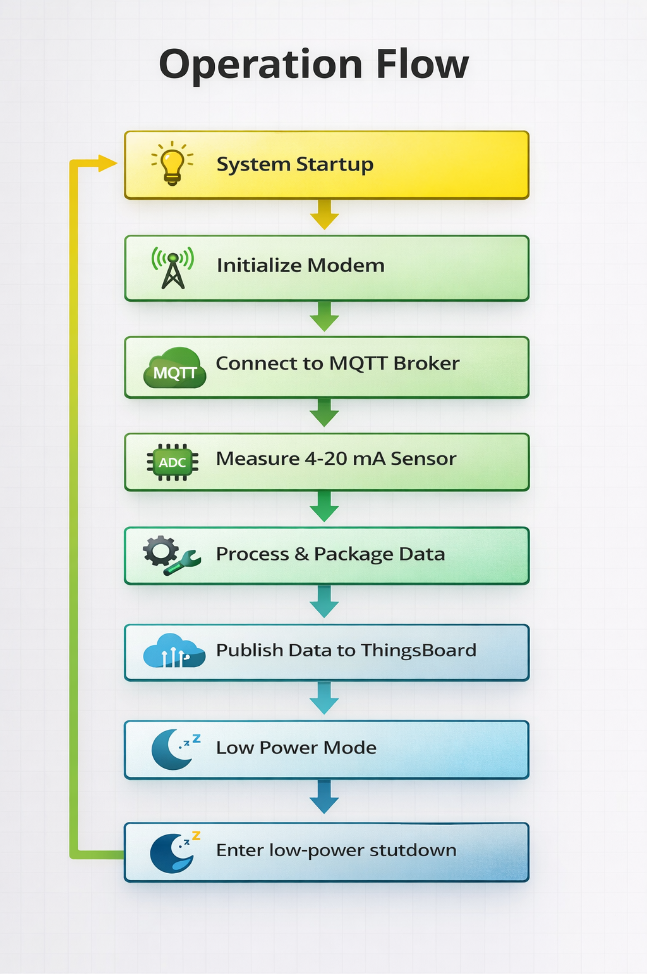
When the device operates on battery power, the SIM7070 LTE modem first establishes a 4G network connection. Once the system successfully connects to the network and establishes an MQTT connection with the ThingsBoard broker, it reads data from the diesel fuel tank level sensor via the 4–20 mA analog input. Finally, the system transmits the collected data to the ThingsBoard dashboard for real-time monitoring.
After the data transmission is complete, the modem is powered down, all peripherals are disconnected, the booster power is disabled, and the MCU enters a low-power shutdown (sleep) mode to conserve energy.
| Stage | Description | Typical Duration |
|---|---|---|
| Wake-up | Device powers up and initializes modem | 1 min |
| Sensor Read | Diesel Fuel Tank Level Sensor 4-20mA analog input read | 2.5 seconds |
| Data Send | Publish Fuel level, battery level and error states to Thingsboard via 4G network | 5 seconds |
| Sleep | Shutdown Mode | 15 minutes |
Power Consumption Analysis #
Power consumption of the system can divided into three main stages
- Initialize the modem and connect to network.
- Read 4-20mA Analog sensor and send data.
- MCU sleep mode (Shutdown mode)
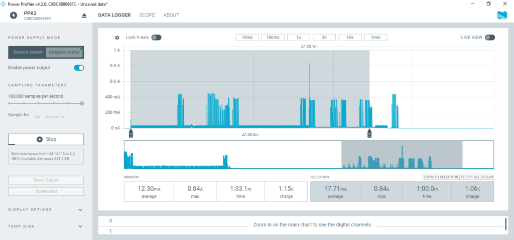
Initialize the modem and connect to network #
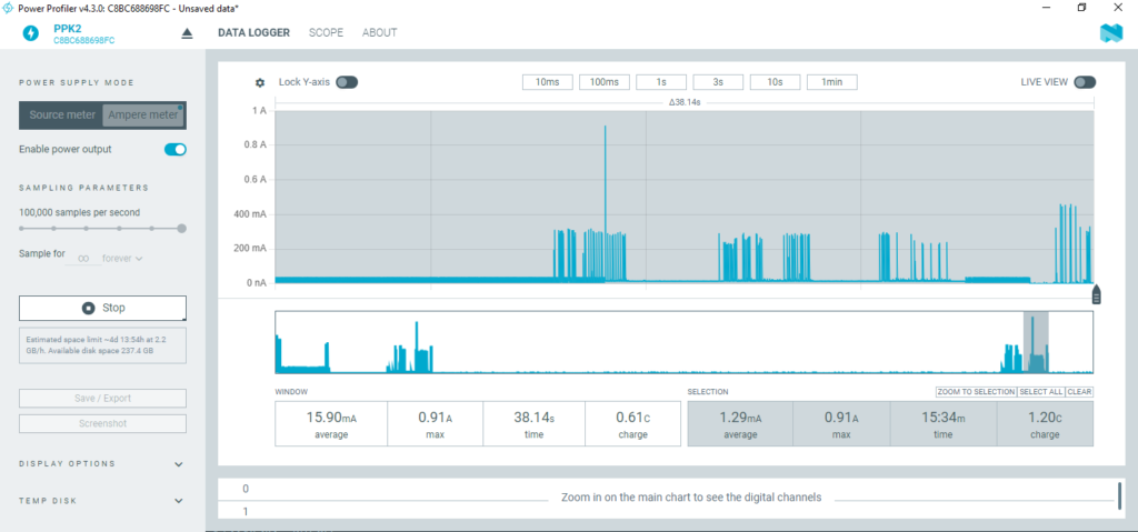
During the modem initialization process, the system experiences its highest current consumption. On average, a current of approximately 17.71mA flows for about one minute. The SIM7070 LTE modem connects to the 4G network during this period, drawing several high current spikes reaching up to 0.84A. However, with two lithium batteries in parallel, the system can adequately supply this demand.
A tantalum capacitor (1000 µF) placed close to the modem acts as a local energy reservoir, supplying the instantaneous surge current while the batteries maintain the average load.
According to the ER34615H (D) lithium primary battery datasheet, each cell can deliver a maximum pulse current of 300 mA for 100 milliseconds every 2 minutes. Based on power profile observations, the modem’s initialization phase produces current pulses exceeding 300 mA, lasting 30–40 milliseconds each. These pulses are within the battery’s safe operating capability, allowing the modem to initialize and operate reliably without excessive voltage drop or battery stress.
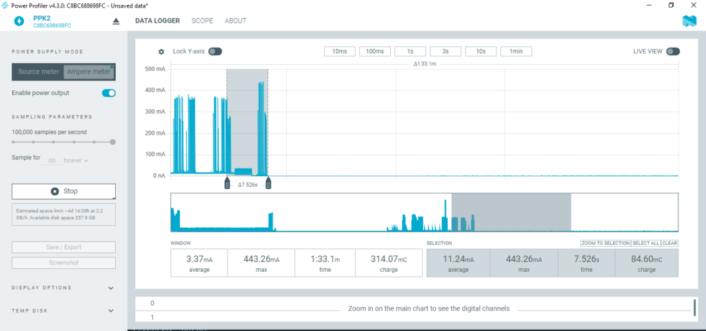
Read 4-20mA Analog sensor and send data #
During this process, the system reads data from the Diesel Fuel Tank Level Sensor via the 4-20mA analog input and transmits the diesel level percentage, diesel level height, battery level and error state readings to ThingsBoard over the 4G network.
At this stage, the system draws an average current of approximately 11.24 mA for a duration of around 7.5 seconds.
MCU sleep mode (Shutdown mode) #
After data transmission is complete, the MCU enters shutdown mode, during which most peripherals and system clocks are powered down. Only the RTC (Real-Time Clock) remains active to keep track of time.
In this mode, the system draws a very low current of approximately 1.05µA for a duration of 15 minutes. Occasional short current spikes between 2mA and 2.85mA occur due to RTC maintenance activity. These spikes are negligible and do not impact the battery performance, as the lithium battery can safely tolerate up to 300 mA pulse currents for 100 milliseconds, according to its specifications.
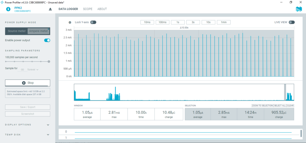
Below figure shows the whole system’s power profile which indicates the average current flow of 1.29mA. It has charge of 1.20c.
| Stage | Mode | Average Current | Duration | Charge | Energy | Max Current |
|---|---|---|---|---|---|---|
| Modem initialization | Shutdown | 17.71mA | 1 min | 1.06C | 3.93 J | 840mA |
| Data send | Shutdown | 11.24mA | 7.52 sec | 84.60mC | 0.31 J | 443mA |
| Sleep (15 min) | Shutdown | 1.05µA | 15 min | 905.52µC | 0.0035 J | 2.85mA |
| Send +sleep | Shutdown | 1.29mA | 16.07min | 1.20 C | 4.60 J | 840mA |
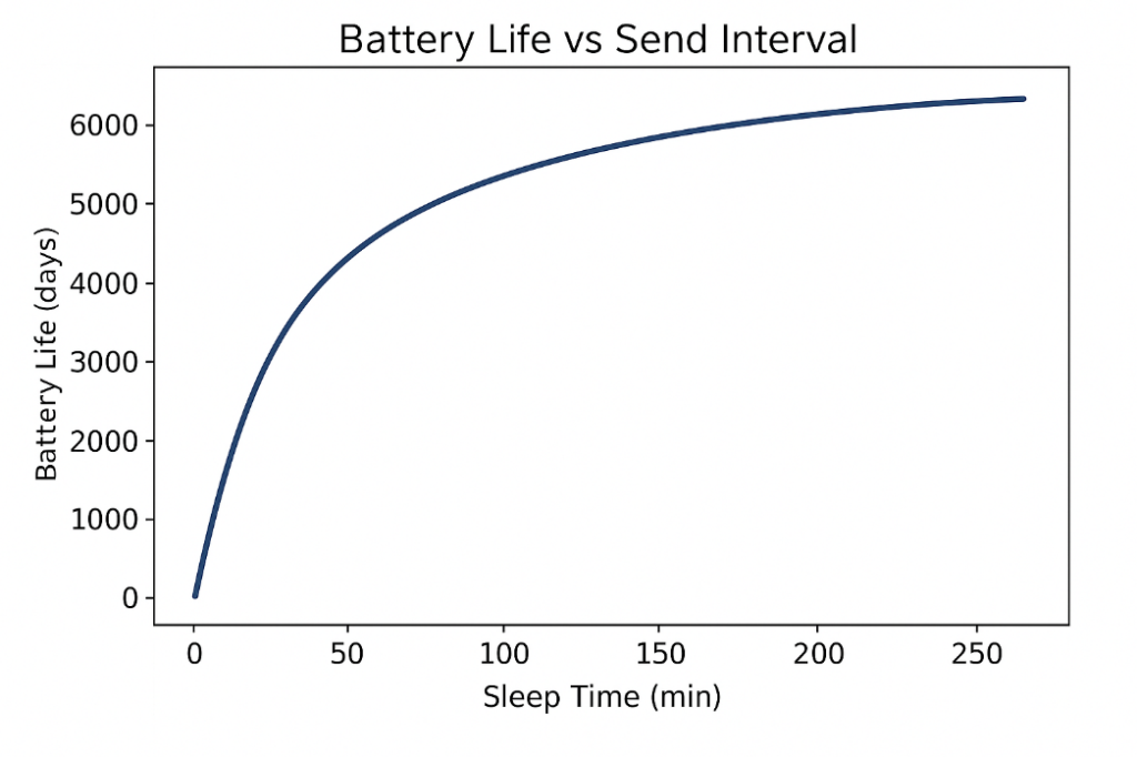
Battery Life Estimation #
EC0-M12-BC-C6-C-A consists of two 19,000 mAh . So it has total 38,000 mAh battery power. As for the above colleted data we have obtained battery life estimation when data send in every 15 minutes and every 1 hour.
| Interval | Average Current per cycle | Estimated life (Hours) | Days | Months | Years |
|---|---|---|---|---|---|
| Every 15 minutes | 1.29mA | 29457.364 h | 1227.39 days | 40.91months | 3.36 years |
| Every 1 hour | 380µA | 100000 h | 4166.66 days | 138.88months | 11.4 years |
Below shows the formula to calculate average current and battery life for different intervals which help you to estimate the battery life for your application.
Key Points and Discussion #
- Optimized Duty Cycling for Extended Battery Life
- Increasing the data transmission interval from 15 minutes to 1 hour extends battery life by approximately 3.4×.
- This demonstrates the benefits of optimized duty cycling: reducing transmission frequency significantly minimizes power consumption while maintaining reliable monitoring.
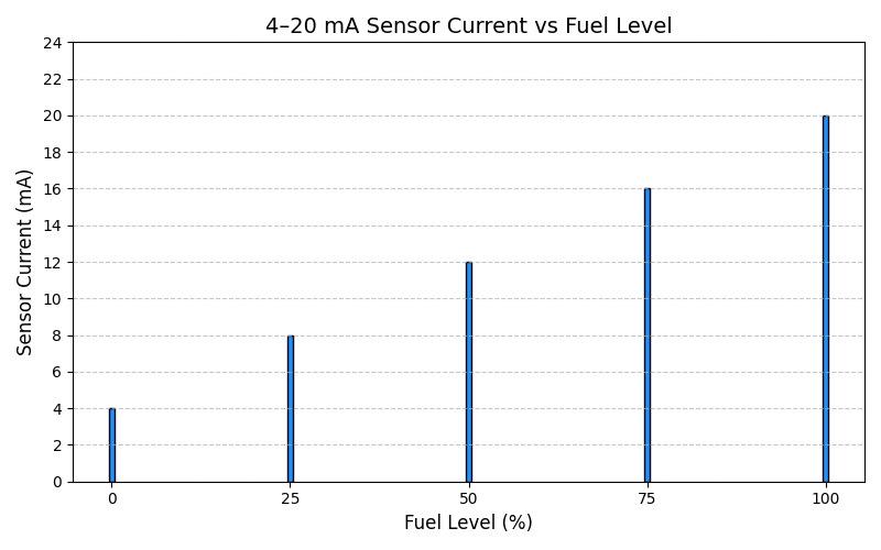
- Sensor Power Consumption Impact
- The 4–20 mA Diesel Fuel Tank Level Sensor draws 4–20 mA, depending on the level and load.
- Overall battery life is influenced by the sensor current; sensors with higher current reduce total operation time.
- Cellular Network Considerations
- Cellular signal strength directly affects modem current during initialization.
- Poor signal conditions may require higher current and additional time to establish a network connection.
- Repeated reconnections due to weak signal increase overall energy consumption.
- Low-Power Operation
- After each data transmission, the device disables ADC, communication interfaces, and booster circuitry, then enters low-power shutdown mode.
- During shutdown, the STM32 MCU and peripherals consume only a few microamps, allowing battery operation for months to years.
- This makes the EC-M12-BC-C6-C-A ideal for remote, low-power industrial monitoring applications.
- Sensor Fault Detection
- The system monitors for open or short circuits in the 4–20 mA sensor, ensuring reliable data logging.
- Fault detection helps prevent incorrect telemetry readings and unnecessary battery drain.
- Practical Application Notes
- The EC-M12-BC-C6-C-A is optimized for long-term deployment in diesel fuel tanks or similar industrial setups.
- Combining low-power MCU operation, duty-cycled data transmission, and efficient sensor interfacing ensures extended battery life and reliable data delivery.


