
Introduction #
Connecting ESP32 to Thingsboard over WiFi. The NORVI-IIOT, powered by the ESP32-WROOM32 microcontroller, connects to the ThingsBoard IoT platform using Wi-Fi and the MQTT protocol. It reads modbus readings(via RS485) and sends this data securely to ThingsBoard, where users can monitor real-time values through customizable dashboards. This setup allows remote access to sensor data, enabling easy monitoring and management without the need for physical device interaction.
What is NORVI IIOT #
NORVI IIoT is a compact, industrial-grade ESP32 controller designed for modern automation and IIoT applications. It enables real-time monitoring, seamless system control, and supports flexible expansion.
NORVI IIoT comes equipped with a high-performance ESP32-WROOM32 module, a built-in 0.96″ OLED display, and a front panel button for easy interaction. It supports multiple digital and analog inputs, relay outputs, and DIN-rail mounting, while also offering an expansion port for additional modules, providing flexibility and scalability for diverse industrial applications.
Note: Specs vary on models
System Architecture #
The system architecture of the NORVI-IIOT device integrated with ThingsBoard is designed to enable seamless, real-time monitoring of Modbus readings using secure wireless communication. The core components and data flow are as follows:
- NORVI-IIOT Device
At the core of the system is the NORVI-IIOT device, equipped with the ESP32-WROOM32 microcontroller. This device continuously reads Modbus readings from connected sensors or inputs. - Wi-Fi Connectivity
The ESP32 module establishes a Wi-Fi connection to the local network, providing internet access required for cloud communication. - MQTT Communication Protocol
Using the lightweight MQTT protocol, the NORVI-IIOT device publishes the modbus data as telemetry messages to the ThingsBoard MQTT broker. MQTT ensures reliable and efficient data transmission with minimal bandwidth consumption. - ThingsBoard IoT Platform
ThingsBoard acts as the cloud-based platform for device management, data ingestion, processing, and visualization. It receives the MQTT messages, stores telemetry data, and displays the modbus readings on customizable dashboards. - User Interface
End users can access the ThingsBoard web interface or mobile app to monitor live sensor data, configure alerts, and analyze historical measurements remotely.
ThingsBoard Setup #
To successfully visualize Modbus readings from the NORVI-IIOT device, the ThingsBoard platform must be properly configured. This section outlines the key steps to set up ThingsBoard for device management and data visualization.
Create a ThingsBoard Account and Log In
- Register for a ThingsBoard cloud account or install a local ThingsBoard server.
- Log in to your ThingsBoard dashboard using your credentials.
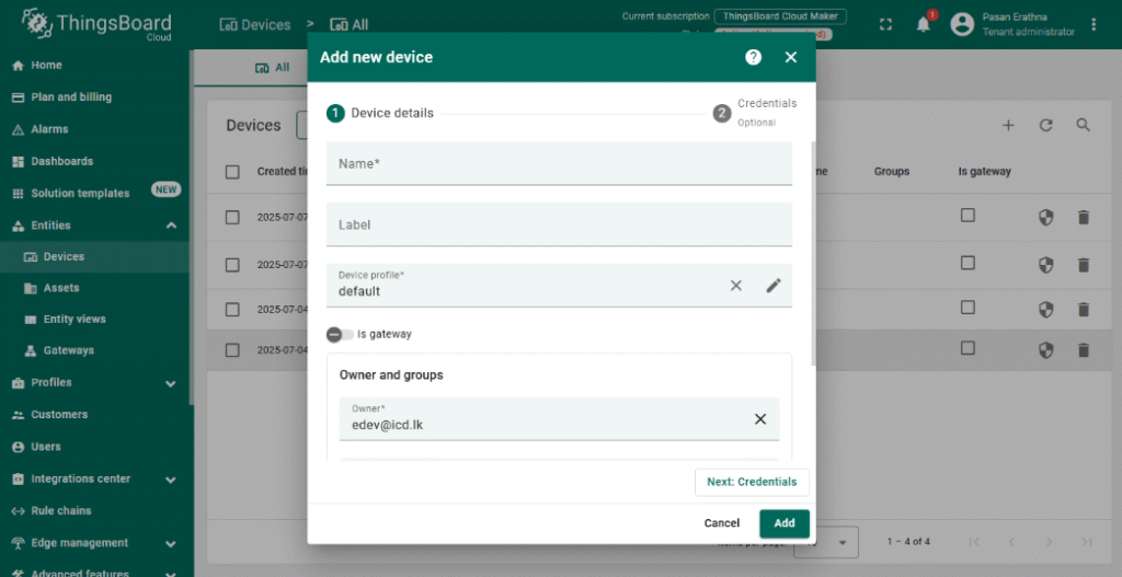
Add a New Device #
- Navigate to Devices and click + Add new device.
- Provide a meaningful name for your NORVI-IIOT device (e.g., “NORVI IIOT – Modbus RS485”).
- Save the device; this generates a unique Access Token used for MQTT authentication.
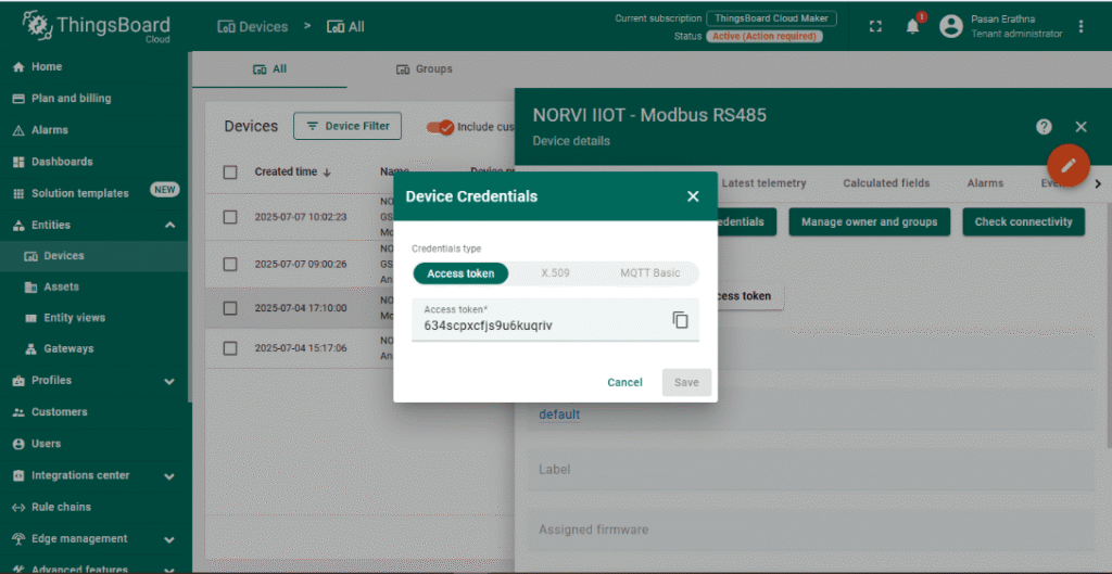
Configure Device Credentials #
- Open the newly created device and go to the Manage credentials tab.
- Copy the Access Token; this token will be used in the ESP32 MQTT client to authenticate the device.
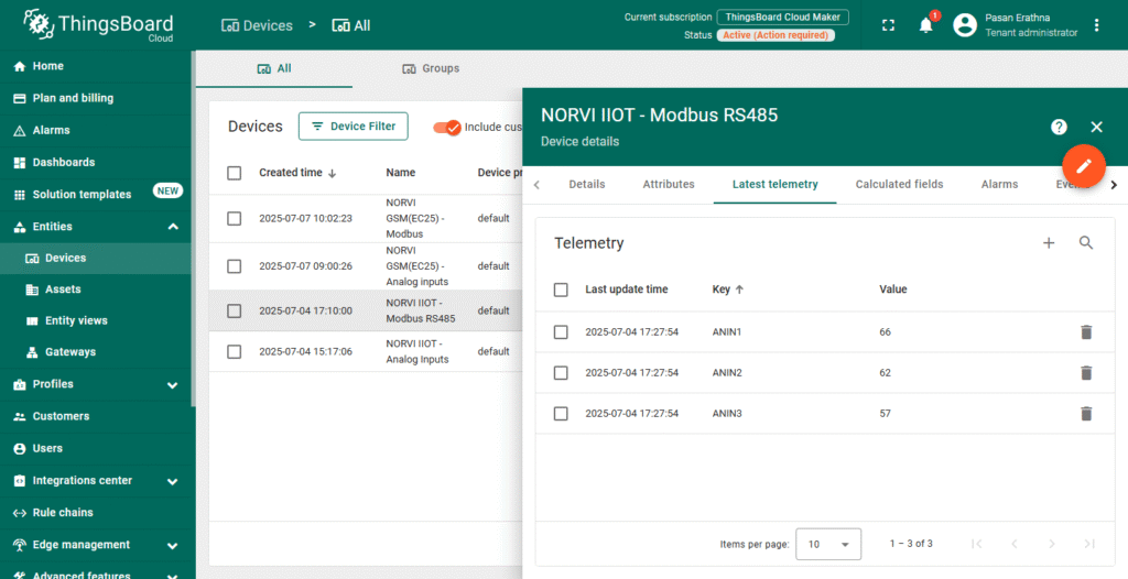
Set Up Telemetry Data #
- ThingsBoard automatically accepts telemetry data sent via MQTT.
- Your device will publish Modbus readings as telemetry using JSON format (e.g., {“ANIN”: 66}).
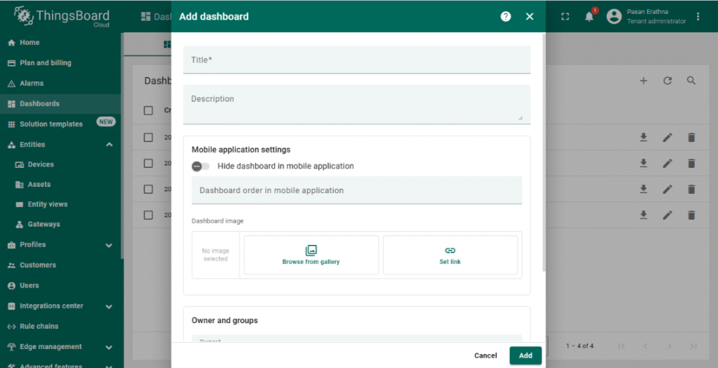
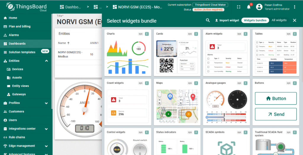
Create a Dashboard for Visualization #
- Go to the Dashboards section and click + Add new dashboard.
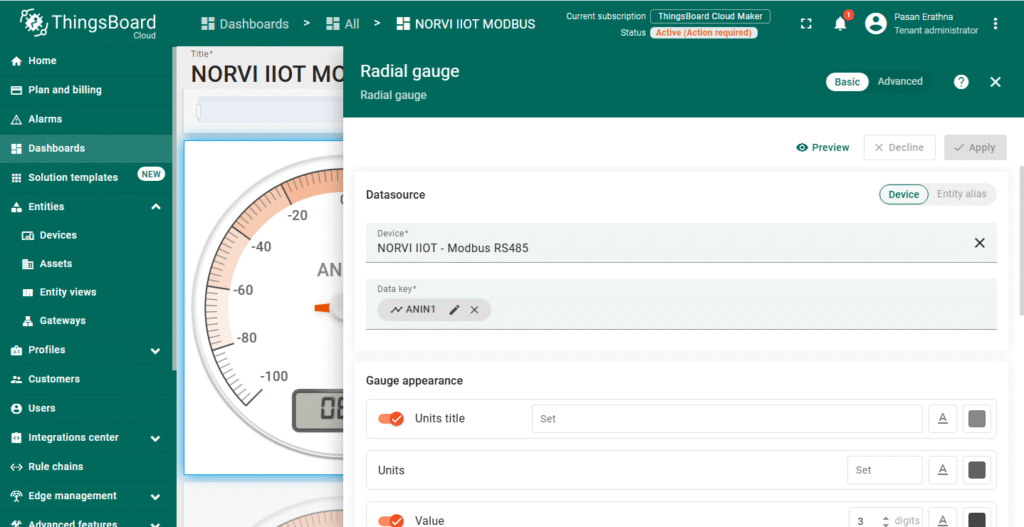
- Design a dashboard by adding widgets such as charts, gauges, or numeric displays.
- Link widgets to the NORVI-IIOT device telemetry keys (e.g., ANIN1) to visualize real-time Modbus data.
Optional: Set Alerts and Rules #
- Configure rules to trigger alerts or actions based on input thresholds or device status.
- Use ThingsBoard’s rule engine to automate notifications or device commands.
With ThingsBoard configured, the NORVI-IIOT device can securely send Modbus data over MQTT, enabling real-time monitoring and analysis through intuitive dashboards.
Software Setup #
- Install the ESP32 board in Arduino IDE:
- Go to File > Preferences.
- Go to Tools > Boards > Boards Manager, search for “ESP32”, and install.
- NORVI-with-ThingsBoard
- Install Required Libraries (Arduino):
- Go to Sketch > Include Library > Manage Libraries and install:
- WiFi.h
- PubSubClient.h
- ModbusMaster.h
- Go to Sketch > Include Library > Manage Libraries and install:
- Configure the code:
Code Explanation #
Library Inclusions and Definitions #
- WiFi.h – Connects ESP32 to Wi-Fi.
- PubSubClient.h – Handles MQTT communication with ThingsBoard.
- ModbusMaster.h – Reads data from Modbus RTU devices via RS485.
- RXD / TXD – Serial pins for RS485 communication.
- FC – Flow control pin for enabling/disabling RS485 driver.
#include <WiFi.h>
#include <PubSubClient.h>
#include <ModbusMaster.h>
#define RXD 13
#define TXD 2
#define FC  4
Wi-Fi and ThingsBoard Credentials #
- Wi-Fi SSID and password allow the ESP32 to connect to the local network.
- ThingsBoard server details, port (default MQTT port 1883), and the device token authenticate the device on ThingsBoard.
const char* ssid = "username";
const char* password = "password";

const char* thingsboardServer = "thingsboard.cloud";
const int mqttPort = 1883;
const char* token = " 634scpxcfjs9u6kuqriv"; // MQTT access token from ThingsBoard device
Modbus RS485 Setup #
- ModbusMaster node – Modbus RTU communication object.
- preTransmission/postTransmission – Control RS485 transceiver direction (send/receive).
ModbusMaster node;

void preTransmission() { digitalWrite(FC, 1); }
void postTransmission() { digitalWrite(FC, 0); }
Wi-Fi Connection Function
void connectWiFi() {
  WiFi.begin(ssid, password);
  Serial.print("Connecting to WiFi");
  while (WiFi.status() != WL_CONNECTED) {
    delay(500); Serial.print(".");
  }
  Serial.println("\nWiFi connected!");
}
MQTT Connection Function #
void connectMQTT() {
  while (!client.connected()) {
    Serial.print("Connecting to ThingsBoard MQTT...");
    if (client.connect("ESP32Client", token, NULL)) {
      Serial.println("connected!");
    } else {
      Serial.print("failed with state ");
      Serial.println(client.state());
      delay(2000);
    }
  }
}
Sending Telemetry Data #
- Reads 3 holding registers starting at address 0x40001.
- Extracts each register value (IN1, IN2, IN3)
- Constructs a JSON string payload with modbus readings (ANIN1 to ANIN3).
- Publishes telemetry data to ThingsBoard MQTT topic “v1/devices/me/telemetry”.
void sendTelemetry() {

  uint8_t value;
  uint8_t IN1, IN2, IN3, IN4;
  value = node.readHoldingRegisters(0x40001, 3);

  IN1 = node.getResponseBuffer(0x00);
  IN2 = node.getResponseBuffer(0x01);
  IN3 = node.getResponseBuffer(0x02);

  Serial.print("\n");
  Serial.print(" ANIN1 : ");
  Serial.print(IN1);
  Serial.print(" ANIN2 : ");
  Serial.print(IN2);
  Serial.print(" ANIN3 : ");
  Serial.print(IN3);
  Serial.print("\n");
  delay(500);


  String payload = "{\"ANIN1\":";
  payload += IN1;
  payload += ", \"ANIN2\":";
  payload += IN2;
  payload += ", \"ANIN3\":";
  payload += IN3;
  payload += "}";

  Serial.print("Publishing: ");
  Serial.println(payload);

  client.publish("v1/devices/me/telemetry", payload.c_str());
}
Setup Function #
- Initializes serial communication for debug output.
- Connects to Wi-Fi.
- Configures MQTT server.
- Initializes RS485 pins, and Modbus communication.
void setup() {
  Serial.begin(9600);
  delay(100);
  connectWiFi();
  delay(1000);
  client.setServer(thingsboardServer, mqttPort);
  delay(1000);

  pinMode(FC, OUTPUT);
  digitalWrite(FC, 0);

  Serial1.begin(9600, SERIAL_8N1, RXD, TXD);

  node.begin(1, Serial1);                           //Slave ID as 1
  node.preTransmission(preTransmission);
  delay(10);
  node.postTransmission(postTransmission);
}
Main Loop #
- Keeps MQTT connection alive, reconnects if disconnected.
- Calls client.loop() to maintain MQTT client state.
- Sends telemetry every 5 seconds.
void loop() {
  if (!client.connected()) {
    connectMQTT();
  }

  client.loop();

  if (millis() - lastSend > 5000) {
    lastSend = millis();
    sendTelemetry();
  }
}
Testing Setup #
Upload the Firmware #
Compile and upload the firmware to the ESP32 and check the serial monitor output and verify that device is connected to the Wifi and ThingsBoard MQTT.
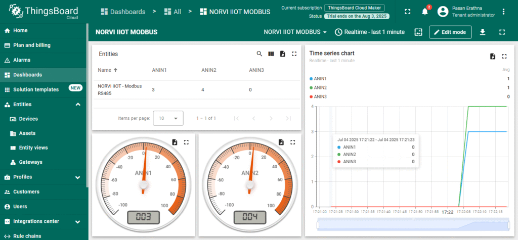
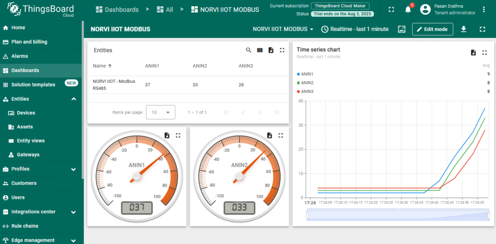
Expected Outputs #
ESP32 logs network connection and update status. Check ThingsBoard dashboard to confirm it displays correct Modbus readings.
Common Issues & Fixes #
| Issue | Possible Cause | Solution |
|---|---|---|
| Wi-Fi not connecting | Incorrect SSID or password; weak signal | Verify credentials in code, ensure router is on and within range |
| MQTT connection failure | Wrong server/port; invalid Access Token | Check ThingsBoard server address and port; confirm Access Token matches device in ThingsBoard |
| No Modbus data received | Wrong slave ID or register address in code | Verify the Modbus slave ID and register addresses with your device’s documentation and update node.begin() and readHoldingRegisters() accordingly. |
| Data updates delayed or missing | Long send interval; Wi-Fi dropouts | Reduce telemetry interval in code; check Wi-Fi stability |
| All values show 0 | RS485 wiring reversed (A/B swapped) | Swap the A/B lines between NORVI-IIOT and Modbus device. |
| No Modbus readings on dashboard | Widget keys don’t match telemetry keys | Ensure ThingsBoard widget keys match JSON keys (ANIN1, etc.) sent by device |


