Introduction: Industrial Sensors Meet IoT Power
Interfacing 0-10V analog sensors with ESP32 microcontrollers bridges the gap between industrial-grade sensing and modern IoT connectivity. This comprehensive guide shows you exactly how to safely connect industrial 0-10V sensors to ESP32, protecting your board while achieving accurate measurements.
Whether you’re monitoring temperature, pressure, humidity, or light levels, 0-10V sensors are the industrial standard. Combined with ESP32’s WiFi and Bluetooth capabilities, you create powerful IoT monitoring systems at a fraction of traditional costs.
Understanding 0-10V Analog Sensors
What Are 0-10V Analog Sensors?
0-10V analog sensors are industrial-standard devices that output voltage signals proportional to measured parameters. The voltage range directly represents the measurement:
- 0V = Minimum reading (0% scale)
- 5V = Mid-range reading (50% scale)
- 10V = Maximum reading (100% scale)
Common Applications:
- Temperature transmitters (0-100°C)
- Humidity sensors (0-100% RH)
- Pressure transducers (0-100 PSI)
- Light level sensors (0-1000 lux)
- CO2 monitors (0-2000 ppm)
- Distance sensors (0-10 meters)
Why 0-10V is Industry Standard
Advantages of 0-10V Sensors:
Widespread Compatibility: Nearly universal in industrial automation, HVAC systems, and building management.
Simple Implementation: Direct voltage measurement requires minimal signal conditioning compared to current loops.
Cost-Effective: Generally, less expensive than 4-20mA sensors for many applications.
Adequate Noise Immunity: Better than low-voltage signals for moderate-distance transmission (up to 100 meters with proper cabling).
Easy Troubleshooting: Voltage measurements are simple with standard multimeters.
The ESP32 Challenge: 3.3V Limitation
Why Direct Connection Doesn’t Work?
ESP32 analog input pins have a critical limitation: maximum input voltage of 3.3V. Applying 10V directly will permanently damage your ESP32 board.
ESP32 ADC Specifications:
- Maximum safe voltage: 3.3V
- ADC resolution: 12-bit (0-4095)
- ADC channels: 18 pins (ADC1 and ADC2)
- Recommended pins: GPIO 32, 33, 34, 35, 36, 39
The Problem:
0-10V sensor output → ESP32 (3.3V max) = ⚠️ DAMAGE!The Solution: Use a voltage divider circuit to scale 10V down to 3.3V safely.
Building the Voltage Divider Circuit
Components You’ll Need
Essential Components:
- ESP32 development board or NORVI controller
- 0-10V analog sensor
- Resistor R1: 68kΩ (1/4W, 1% tolerance)
- Resistor R2: 33kΩ (1/4W, 1% tolerance)
- Breadboard or PCB
- Jumper wires
- 12-24VDC power supply (for sensor)
- 100nF ceramic capacitor (noise filtering)
Optional Protection:
- 3.6V Zener diode (overvoltage protection)
- 10kΩ pull-down resistor
- Schottky diode (reverse polarity protection)
Voltage Divider Calculation
The voltage divider formula reduces 10V to safe 3.3V levels:
Formula:
Vout = Vin × (R2 / (R1 + R2))Calculation:
R1 = 68kΩ
R2 = 33kΩ

Vout = 10V × (33kΩ / (68kΩ + 33kΩ))
Vout = 10V × (33kΩ / 101kΩ)
Vout = 10V × 0.327
Vout = 3.27V ✓ (Safe for ESP32!)
Voltage Scaling Table:
| Sensor Output | Divided Voltage | ESP32 Reads |
|---|---|---|
| 0V | 0V | 0 ADC |
| 2V | 0.65V | 819 ADC |
| 5V | 1.63V | 2048 ADC |
| 7V | 2.29V | 2867 ADC |
| 10V | 3.27V | 4095 ADC |
Circuit Diagram
                  Sensor Output (0-10V)
                           |
                           |
                    ┌──────┴──────┐
                    │             │
                   R1             │
                  68kΩ            │
                    │             │
                    ├─────────────┼──→ ESP32 GPIO 36
                    │             │     (ADC1_CH0)
                   R2          100nF
                  33kΩ        (Filter)
                    │             │
                    └──────┬──────┘
                           │
                          GND
Step-by-Step Wiring:
- Connect sensor positive output to R1 (68kΩ)
- Connect other R1 end to junction point
- Connect R2 (33kΩ) from junction to ground
- Connect junction point to ESP32 GPIO 36
- Connect 100nF capacitor between GPIO 36 and ground
- Connect sensor ground to ESP32 ground (common ground!)
- Power sensor with appropriate voltage (12-24V typically)
Programming the ESP32
Basic Arduino Code
// 0-10V Analog Sensor Interface with ESP32
const int SENSOR_PIN = 36;  // GPIO 36 (ADC1_CH0)

// Voltage divider resistor values
const float R1 = 68000.0;  // 68kΩ
const float R2 = 33000.0;  // 33kΩ

// ESP32 ADC specifications
const float ESP32_ADC_MAX = 4095.0;  // 12-bit
const float ESP32_VREF = 3.3;        // Reference voltage

void setup() {
  Serial.begin(115200);

  // Configure ADC
  analogReadResolution(12);           // 12-bit resolution
  analogSetAttenuation(ADC_11db);     // 0-3.3V range

  Serial.println("0-10V Sensor Reader Started");
}

float readSensorVoltage() {
  // Read raw ADC value
  int rawADC = analogRead(SENSOR_PIN);

  // Convert to measured voltage (after divider)
  float measuredVoltage = (rawADC / ESP32_ADC_MAX) * ESP32_VREF;

  // Calculate original sensor voltage (before divider)
  float sensorVoltage = measuredVoltage * ((R1 + R2) / R2);

  return sensorVoltage;
}

void loop() {
  float voltage = readSensorVoltage();

  Serial.print("Sensor Voltage: ");
  Serial.print(voltage, 2);
  Serial.println(" V");

  delay(1000);
}
Converting to Engineering Units
Convert voltage readings to actual measurement values:
// Example: Temperature Sensor (0-100°C mapped to 0-10V)
float voltageToTemperature(float voltage) {
  // Map 0-10V to 0-100°C
  float temperature = (voltage / 10.0) * 100.0;
  return temperature;
}

// Example: Humidity Sensor (0-100% RH mapped to 0-10V)
float voltageToHumidity(float voltage) {
  // Map 0-10V to 0-100% RH
  float humidity = (voltage / 10.0) * 100.0;
  return humidity;
}

// Generic conversion function
float voltageToValue(float voltage, float minValue, float maxValue) {
  // Map voltage to any sensor range
  float normalizedVoltage = voltage / 10.0;  // 0-1 scale
  float value = (normalizedVoltage * (maxValue - minValue)) + minValue;
  return value;
}

void loop() {
  float voltage = readSensorVoltage();

  // Convert to temperature (0-100°C range)
  float temperature = voltageToValue(voltage, 0.0, 100.0);

  Serial.print("Temperature: ");
  Serial.print(temperature, 1);
  Serial.println(" °C");

  delay(1000);
}
Advanced Code with Filtering
Improve accuracy with averaging and filtering:
// Moving Average Filter
const int FILTER_SAMPLES = 10;
float readings[FILTER_SAMPLES];
int readIndex = 0;
float total = 0;

float readFilteredVoltage() {
  // Remove oldest reading
  total = total - readings[readIndex];

  // Read new voltage
  float newVoltage = readSensorVoltage();

  // Store new reading
  readings[readIndex] = newVoltage;
  total = total + newVoltage;

  // Advance index
  readIndex = (readIndex + 1) % FILTER_SAMPLES;

  // Calculate average
  float average = total / FILTER_SAMPLES;
  return average;
}

void setup() {
  Serial.begin(115200);
  analogReadResolution(12);
  analogSetAttenuation(ADC_11db);

  // Initialize filter array
  for (int i = 0; i < FILTER_SAMPLES; i++) {
    readings[i] = 0;
  }

  Serial.println("Filtered 0-10V Reader Started");
}

void loop() {
  float voltage = readFilteredVoltage();
  float temperature = voltageToValue(voltage, 0.0, 100.0);

  Serial.print("Filtered Voltage: ");
  Serial.print(voltage, 2);
  Serial.print(" V | Temperature: ");
  Serial.print(temperature, 1);
  Serial.println(" °C");

  delay(500);
}
Wi-Fi Dashboard Integration
Create a web-based monitoring dashboard:
#include <WiFi.h>
#include <WebServer.h>

const char* ssid = "YourWiFi";
const char* password = "YourPassword";

WebServer server(80);
float currentVoltage = 0;
float currentTemperature = 0;

void handleRoot() {
  String html = "<!DOCTYPE html><html>";
  html += "<head><meta name='viewport' content='width=device-width, initial-scale=1'>";
  html += "<style>body{font-family:Arial;text-align:center;margin:50px;}";
  html += ".reading{font-size:48px;color:#0066cc;font-weight:bold;}";
  html += ".label{font-size:24px;color:#666;margin-top:20px;}</style>";
  html += "<script>setInterval(function(){fetch('/data').then(r=>r.json())";
  html += ".then(d=>{document.getElementById('voltage').innerHTML=d.voltage.toFixed(2);";
  html += "document.getElementById('temp').innerHTML=d.temp.toFixed(1);})},1000);</script>";
  html += "</head><body>";
  html += "<h1>0-10V Sensor Monitor</h1>";
  html += "<div class='label'>Voltage</div>";
  html += "<div class='reading'><span id='voltage'>--</span> V</div>";
  html += "<div class='label'>Temperature</div>";
  html += "<div class='reading'><span id='temp'>--</span> °C</div>";
  html += "</body></html>";

  server.send(200, "text/html", html);
}

void handleData() {
  String json = "{\"voltage\":" + String(currentVoltage, 2);
  json += ",\"temp\":" + String(currentTemperature, 1) + "}";
  server.send(200, "application/json", json);
}

void setup() {
  Serial.begin(115200);
  analogReadResolution(12);
  analogSetAttenuation(ADC_11db);

  // Connect to WiFi
  WiFi.begin(ssid, password);
  while (WiFi.status() != WL_CONNECTED) {
    delay(500);
    Serial.print(".");
  }
  Serial.println("\nConnected!");
  Serial.println(WiFi.localIP());

  // Setup web server
  server.on("/", handleRoot);
  server.on("/data", handleData);
  server.begin();
}

void loop() {
  server.handleClient();

  // Update readings
  currentVoltage = readFilteredVoltage();
  currentTemperature = voltageToValue(currentVoltage, 0.0, 100.0);

  delay(100);
}
Calibration and Testing
Two-Point Calibration
Improve accuracy with calibration:
// Calibration values
float cal_voltage_low = 0.0;   // Known low voltage
float cal_adc_low = 0.0;        // ADC reading at low
float cal_voltage_high = 10.0;  // Known high voltage
float cal_adc_high = 4095.0;    // ADC reading at high

float calibratedVoltage(int rawADC) {
  // Linear calibration between two points
  float slope = (cal_voltage_high - cal_voltage_low) /
                (cal_adc_high - cal_adc_low);
  float voltage = slope * (rawADC - cal_adc_low) + cal_voltage_low;
  return voltage;
}

void performCalibration() {
  Serial.println("=== Calibration Mode ===");

  // Step 1: Apply 0V
  Serial.println("Apply 0V and press Enter...");
  while (!Serial.available()) delay(100);
  Serial.read();
  cal_adc_low = analogRead(SENSOR_PIN);
  Serial.print("Low ADC: ");
  Serial.println(cal_adc_low);

  // Step 2: Apply 10V
  Serial.println("Apply 10V and press Enter...");
  while (!Serial.available()) delay(100);
  Serial.read();
  cal_adc_high = analogRead(SENSOR_PIN);
  Serial.print("High ADC: ");
  Serial.println(cal_adc_high);

  Serial.println("Calibration Complete!");
}
Testing Procedure
Step 1: Hardware Verification
- Check all connections with multimeter
- Verify resistor values (should be within 1%)
- Measure voltage at ESP32 pin (must be ≤3.3V)
- Test with known voltage source
Step 2: Software Testing
- Upload code and open serial monitor
- Apply 0V → Should read ~0V
- Apply 5V → Should read ~5V
- Apply 10V → Should read ~10V
- Check for noise and stability
Step 3: Accuracy Check
- Compare ESP32 readings with multimeter
- Expected accuracy: ±2-5% without calibration
- With calibration: ±1-2% accuracy possible
Troubleshooting Common Issues
Problem: Readings Are Unstable
Solutions:
- Add 100nF capacitor between ADC pin and ground
- Increase averaging samples (20-50 samples)
- Use shielded cable for sensor connection
- Check for loose connections
- Verify stable power supply
Problem: Voltage Reads Too High/Low
Causes:
- Wrong resistor values (measure with multimeter)
- ESP32 reference voltage not exactly 3.3V
- Poor connections causing voltage drop
Solutions:
- Use precision 1% resistors
- Measure actual resistor values
- Perform two-point calibration
- Check all solder joints/connections
Problem: ESP32 Not Responding
Check:
- ADC pin not damaged (try different pin)
- Voltage never exceeded 3.3V
- Ground connections are solid
- Power supply is adequate
- Code uploaded successfully
Using NORVI Industrial Controllers
NORVI IIOT series offers 0-10V compatible analog inputs with significant advantages:
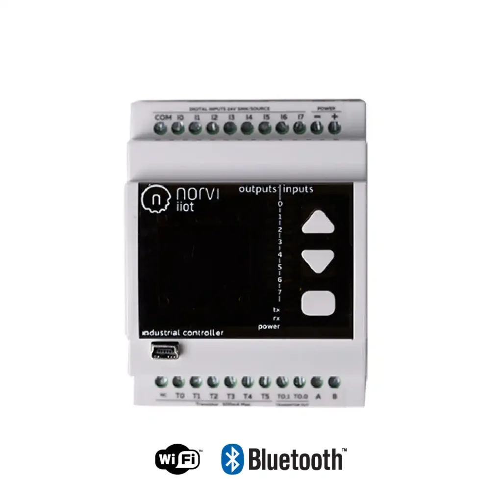
Built-in Features:
- Direct 0-10V input (no external divider needed!)
- 16-bit ADC resolution (vs 12-bit ESP32)
- Electrical isolation for safety
- Industrial-grade protection circuits
- DIN rail mounting
- Professional terminal blocks
Accuracy Comparison:
| Feature | DIY ESP32 | NORVI IIOT |
|---|---|---|
| ADC Resolution | 12-bit (4096 steps) | 16-bit (65536 steps) |
| Accuracy | ±2-5% | ±0.1% |
| Voltage Divider | External required | Built-in |
| Protection | Manual | Industrial grade |
| Mounting | Breadboard | DIN rail |
| Cost | $10-20 + components | $76.99-115.00 (complete) |
When to Choose NORVI:
- Professional installations
- Critical measurements requiring high accuracy
- Industrial environments
- Multiple sensor channels needed
- Long-term reliability essential
- Safety certifications required
Advanced Applications
Multi-Sensor Monitoring
Read multiple 0-10V sensors:
// Multiple sensors on different pins
const int TEMP_SENSOR = 36;
const int HUMIDITY_SENSOR = 39;
const int PRESSURE_SENSOR = 34;

void loop() {
  float temp = readAndConvert(TEMP_SENSOR, 0, 100);     // 0-100°C
  float humidity = readAndConvert(HUMIDITY_SENSOR, 0, 100); // 0-100%
  float pressure = readAndConvert(PRESSURE_SENSOR, 0, 10);  // 0-10 bar

  Serial.printf("Temp: %.1f°C | Humidity: %.1f%% | Pressure: %.2f bar\n",
                temp, humidity, pressure);

  delay(2000);
}
Data Logging to SD Card
#include <SD.h>
#include <SPI.h>

const int SD_CS = 5;

void logData(float voltage, float value) {
  File dataFile = SD.open("/sensor_log.csv", FILE_APPEND);
  if (dataFile) {
    dataFile.print(millis());
    dataFile.print(",");
    dataFile.print(voltage, 2);
    dataFile.print(",");
    dataFile.println(value, 2);
    dataFile.close();
  }
}
Cloud Integration (MQTT)
#include <PubSubClient.h>

WiFiClient espClient;
PubSubClient mqtt(espClient);

void publishSensorData() {
  float voltage = readFilteredVoltage();
  float temperature = voltageToValue(voltage, 0, 100);

  String payload = "{\"voltage\":" + String(voltage, 2) +
                   ",\"temperature\":" + String(temperature, 1) + "}";

  mqtt.publish("sensors/temperature", payload.c_str());
}
Best Practices and Safety
Electrical Safety
Protection Methods:
- Always use voltage divider for 0-10V sensors
- Add 3.6V Zener diode for overvoltage protection
- Never exceed 3.3V on ESP32 pins
- Use proper grounding
- Isolate high voltage from low voltage
Installation Tips
DO:
- Use quality 1% tolerance resistors
- Add filter capacitors (100nF)
- Test circuit with multimeter first
- Document resistor values used
- Calibrate for best accuracy
DON’T:
- Apply 10V directly to ESP32
- Use carbon resistors (use metal film)
- Forget common ground connection
- Skip testing before deployment
- Ignore noise filtering
Conclusion
Interfacing 0-10V analog sensors with ESP32 opens doors to affordable industrial IoT monitoring. With a simple voltage divider circuit and proper programming, you can safely read industrial sensors while leveraging ESP32’s powerful connectivity features.